JAJSD36 April 2017 INA233
PRODUCTION DATA.
- 1 特長
- 2 アプリケーション
- 3 概要
- 4 改訂履歴
- 5 Pin Configuration and Functions
- 6 Specifications
-
7 Detailed Description
- 7.1 Overview
- 7.2 Functional Block Diagram
- 7.3 Feature Description
- 7.4 Device Functional Modes
- 7.5 Programming
- 7.6
Register Maps
- 7.6.1 PMBus Command Support
- 7.6.2
Standard PMBus Commands
- 7.6.2.1 CLEAR_FAULTS (03h)
- 7.6.2.2 RESTORE_DEFAULT_ALL (12h)
- 7.6.2.3 CAPABILITY (19h)
- 7.6.2.4 IOUT_OC_WARN_LIMIT (4Ah) [default = 01111111 11111000]
- 7.6.2.5 VIN_OV_WARN_LIMIT (57h) [default = 01111111 11111000]
- 7.6.2.6 VIN_UV_WARN_LIMIT (58h) [default = 00000000 00000000]
- 7.6.2.7 PIN_OP_WARN_LIMIT (6Bh) [default = 11111111 11110000]
- 7.6.2.8 STATUS_BYTE (78h)
- 7.6.2.9 STATUS_WORD (79h)
- 7.6.2.10 STATUS_IOUT (7Bh)
- 7.6.2.11 STATUS_INPUT (7Ch)
- 7.6.2.12 STATUS_CML (7Eh)
- 7.6.2.13 STATUS_MFR_SPECIFIC (80h)
- 7.6.2.14 READ_EIN (86h)
- 7.6.2.15 READ_VIN (88h)
- 7.6.2.16 READ_IIN (89h)
- 7.6.2.17 READ_VOUT (8Bh)
- 7.6.2.18 READ_IOUT (8Ch, R)
- 7.6.2.19 READ_POUT (96h, R)
- 7.6.2.20 READ_PIN (97h, R)
- 7.6.2.21 MFR_ID (99h)
- 7.6.2.22 MFR_MODEL (9Ah)
- 7.6.2.23 MFR_REVISION (9Bh)
- 7.6.3
Manufacturer-Specific PMBus Commands
- 7.6.3.1 MFR_ADC_CONFIG (D0h) [default = 01000001 00100111]
- 7.6.3.2 MFR_READ_VSHUNT (D1h) [default = 00000000 00000000]
- 7.6.3.3 MFR_ALERT_MASK (D2h) [default = XXXXXXXX 11110000]
- 7.6.3.4 MFR_CALIBRATION (D4h) [default = 00000000 00000001]
- 7.6.3.5 MFR_DEVICE_CONFIG (D5h) [default = 00000010]
- 7.6.3.6 5.1.1 CLEAR_EIN (D6h)
- 7.6.3.7 TI_MFR_ID (E0h) [value = 01010100 01001001]
- 7.6.3.8 TI_MFR_MODEL (E1h) [value = 00110011 00110011]
- 7.6.3.9 TI_MFR_REVISION (E2h) [value = 01000001 00110000]
- 8 Application and Implementation
- 9 Power Supply Recommendations
- 10Layout
- 11デバイスおよびドキュメントのサポート
- 12メカニカル、パッケージ、および注文情報
1 特長
- 0V~36Vのバス電圧を検出
- ハイサイドまたはローサイドのセンシング
- 電流、電圧、電力を報告
- 内蔵の電力アキュムレータによりエネルギーおよび平均電力を監視
- 高精度:
- ゲイン誤差0.1% (最大値)
- オフセット10µV (最大値)
- 平均化オプションを設定可能
- 電流、バス電圧、電力にそれぞれ独立のアラート制限値
- 1.8V準拠のI2C、SMBus、PMBusインターフェイス
- 16のアドレスをプログラム可能
- 2.7V~5.5V電源で動作
- 10ピンのDGS (VSSOP)パッケージ
2 アプリケーション
- サーバー
- 通信インフラ
- 高性能コンピューティング
- 電力測定
- バッテリ充電器
- 電源
- 試験用機器
3 概要
INA233は、1.8V~5.0Vのデジタル・バス電圧に対応し、I2C、SMBus、PMBus互換のインターフェイスを備えた電流、電圧、電力モニタです。このデバイスは電流、電圧、電力の値を監視し、報告します。内蔵の電力アキュムレータは、エネルギーまたは平均電力の計算に使用できます。較正値、変換時間、平均化オプションをプログラム可能で、内蔵のマルチプライヤと組み合わせて電流のアンペア値や電力のワット値を直接読み出すことができます。
INA233は、電源電圧にかかわらず、0V~36Vの同相バス電圧の電流を検出できます。デバイスは単一の2.7V~5.5V電源で動作し、通常動作で標準310µAの電流を消費します。デバイスは低消費電力のスタンバイ・モードに移行でき、このときの動作電流はわずか2µA (標準値)です。このデバイスは-40℃~+125℃の動作温度範囲で動作が規定されており、最大16のアドレスをプログラム可能です。
製品情報(1)
| 型番 | パッケージ | 本体サイズ(公称) |
|---|---|---|
| INA233 | VSSOP (10) | 3.00mm×3.00mm |
- 利用可能なすべてのパッケージについては、このデータシートの末尾にある注文情報を参照してください。
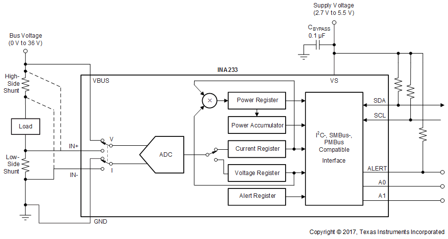
ハイサイドまたはローサイドのセンシング・アプリケーション
