SLAAE26 June 2021 MSP430FR2433
1 Application Brief
Introduction
This design shows how to use MSP430FR2433 to communicate with three kinds of inter-integrated circuit (I2C) sensors on BP-BASSENSORSMKII: including the optical sensor, the temperature sensor and the humidity sensor. The I2C communication speed is set to 100 kHz. This type of functionality is useful for systems that need to detect diffident kinds of environment information, especially in building automation.
Implementation
The key point to realize with this function is to understand the usage of sensors on BP-BASSENSORSMKII. Here, the operation of the three sensors is introduced one by one.
The OPT3001 is a digital ambient light sensor (ALS) that measures the intensity of light as visible by the human eye. For more information on the OPT3001 light sensor, see the OPT3001 product folder.
The TMP117 is a 16-bit digital local temperature sensor that measures the ambient temperature or the temperature of an object in direct contact. In order to use the TMP117, the ribbon cable must be connected. For more information on the TMP117 temperature sensor, see the TMP117 product folder.
The HDC2080 is an integrated temperature and humidity sensor that measures ambient temperature and relative humidity in RH%. Note that V Supply Pin must drive a Logic Low or zero to power the HDC2080. For more information on the HDC2080 humidity sensor, see the HDC2080 product folder. All of these sensors’ output is an I2C- and SMBus-compatible, 2-wire serial interface. Table 1-1 lists the I2C address of these three sensors.
| Device | 7-Bit Address | Hex (7 bit) |
|---|---|---|
| OPT3001 | 1000100 | 44 |
| TMP117 | 1001000 | 48 |
| HDC2080 | 1000000 | 40 |
Table 1-2 lists the pin connections of these three sensors.
| Pin Function | OPT3001 | TMP117 | HDC2080 |
|---|---|---|---|
| I2C SCL | J1.9 | J1.9 | J1.9 |
| I2C SDA | J1.10 | J1.10 | J1.10 |
| V Supply Pin | J1.27 | J1.28 | J1.6 |
| INT Pin | J1.25 | J1.26 | J1.23 |
The hardware connection can refer to Figure 1-1. To run this application, the MSP430FR2433 Launchpad should first be connected to BP-BASSENSORSMKII. Make sure BP-BASSENSORSMKII is in the right direction by checking the pinout on two boards: like 3V3 and GND. Second, connect the related headers on BP-BASSENSORSMKII. J1 should be connected to J27 and J28, to power on the OPT3001 and TMP117. J22 should be connected to J6, to give a zero logic to Q2 to power on the HDC2080. Third, connect ribbon cable to link the TMP117 to the main board. Remember to remove J10 on the launchpad.
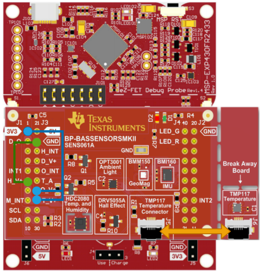 Figure 1-1 Hardware Connection
The I2C communication flow between these three sensors will be different, because they work under different conversion modes. The OPT3001 will be set in continuous conversion mode. Figure 1-2 shows the communication flowchart. The result data is 16 bits. The first read 1byte is high 8 bits. The second read 1 byte is low 8 bits. The high 4 bits of result data is exponent. The low 12 bits is fractional result. To get the final result, the equation (lux = 0.01 × (2E[3:0]) × R[11:0]) needs to be used to decode the data. The unit is Lux.
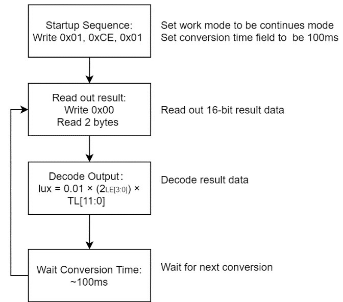 Figure 1-2 OPT3001 I2C Communication
Flowchart
Figure 1-2 OPT3001 I2C Communication
FlowchartFor the TMP117, the default mode is continuous conversion mode. The communication flow chart and the decode equation is shown in Figure 1-3. The result data is 16 bits. The first read 1 byte is high 8 bits. The second read 1 byte is low 8 bits. To be careful, the decoding way will be different when the data above or below 0°C.
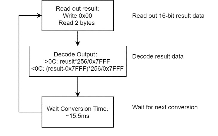 Figure 1-3 TMP117 I2C Communication
Flowchart
Figure 1-3 TMP117 I2C Communication
FlowchartFor the HDC2080, will work under single trigger conversion mode. So, you need to trigger HDC2080 to start the conversion and wait for about 2 ms, until the result is prepared. The result data is 16 bits. The first read 1 byte is high 8 bits. The second read 1 byte is low 8 bit. The communication flow chart and the decode equation is shown in Figure 1-4.
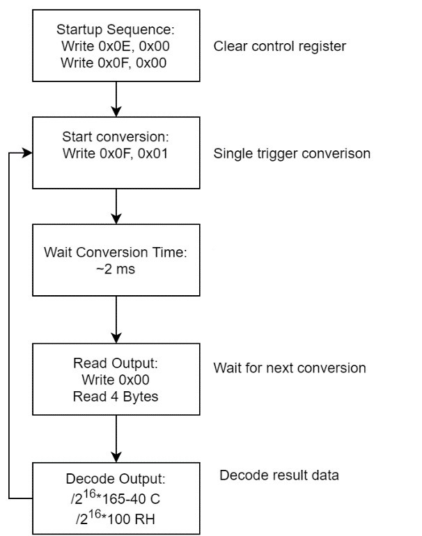 Figure 1-4 HDC2080 I2C Communication
Flowchart
Figure 1-4 HDC2080 I2C Communication
FlowchartAfter a device reset on this application, the MSP430™ MCU sources the subsystem master clock (SMCLK) from the DCO configured to run at 1 MHz. The device then does the peripheral and sensor initialization. Later, the MSP430 keeps accessing data from the OPT3001, TMP117 and HDC2080, one by one. Because the TMP117 and HDC2080 can both sense temperature, you should use TMP117 to sense temperature and use HDC2080 to sense humidity.
To help the customer catch up with the demo, make a GUI show the sensor results. Figure 1-5 shows the block diagram for this implementation. MSP430FR2433 will keep updating data to GUI through back channel universal asynchronous receiver/transmitter (UART).
 Figure 1-5 System Diagram
The MSP430FR2433 LaunchPad™ Development Kit should be used with this example project. Back channel UART interface on eZ-FET is used for UART communication with the GUI. A baud rate of 9600 must be selected with one stop bit and no parity. The COM channel number information can be found in the PC device management under the control panel.
The GUI is used to displays the feedback information from MSP430. Figure 1-6 shows the overview of GUI. On the top of the GUI, there are three text boxes to display the related sensors’ data. On the bottom, there is a button for connection. When the button is clicked, the GUI will send a command to ask for connection and MSP430 will reply sensor data on the related text box.
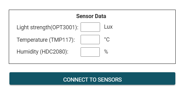 Figure 1-6 I2C Sensor Communication
GUI
Figure 1-6 I2C Sensor Communication
GUITo Get Started
1. Watch the training video “I2C Sensor Communication with a Housekeeping MCU”, to walk through how to use a GUI to show I2C data.
2. Order a MSP430FR2433 LaunchPad kit and BP-BASSENSORSMKII for evaluation.
3. Download and test this example with I2C Sensor Communication GUI.
4. Evaluate the I2C Sensor Communication code for the MSP430FR2433 LaunchPad kit.
Device Recommendations
The device used in this example is part of the MSP430 housekeeping portfolio. This example can be used with the devices shown in Table 1-3 with minimal code changes.
| Part Number | Key Features |
|---|---|
| MSP430FR2433 | 16KB FRAM, 4KB SRAM, 10-bit ADC, UART/SPI/I2C, Timer |
| MSP430FR2422 | 8KB FRAM, 2KB SRAM, 10-bit ADC, UART/SPI/I2C, Timer |
Related Information
- MSP430FR2433 LaunchPad™ Development Kit
- Building automation sensors BoosterPack module
- Texas Instruments: HDC2080 Low-Power Humidity and Temperature Digital Sensor
- Texas Instruments: TMP117 High-Accuracy, Low-Power, Digital Temperature Sensor With SMBus™- and I2C-Compatible Interface
- Texas Instruments: OPT3001 Ambient Light Sensor (ALS)