SLUAAI2 December 2021 ISO5451 , ISO5451-Q1 , ISO5452 , ISO5452-Q1 , ISO5851 , ISO5851-Q1 , ISO5852S , ISO5852S-Q1 , UCC20225 , UCC20225-Q1 , UCC20520 , UCC21220 , UCC21222 , UCC21222-Q1 , UCC21320-Q1 , UCC21520 , UCC21520-Q1 , UCC21521 , UCC21530 , UCC21530-Q1 , UCC21540 , UCC21540-Q1 , UCC21541 , UCC21542 , UCC21710 , UCC21710-Q1 , UCC21732 , UCC21732-Q1 , UCC21736-Q1 , UCC21739-Q1 , UCC21750 , UCC21750-Q1 , UCC21759-Q1 , UCC23313 , UCC23313-Q1 , UCC23511 , UCC23511-Q1 , UCC23513 , UCC23513-Q1 , UCC23514 , UCC5304 , UCC5310 , UCC5320 , UCC5350 , UCC5350-Q1 , UCC5390 , UCC5390-Q1 , UCC5870-Q1
1 Application Brief
Noise is a long-standing enemy of gate drive circuits. Whether it is supply ripple or ringing at the gate of a power FET, noise can cause unpredictable behavior and reduce system reliability. Ferrite beads are one of the tools engineers have to prevent such damage. This method is effective because ferrite beads attenuate high frequency ringing while minimally affecting normal operation. The goal of this application brief is to cover the basics of ferrite beads, the source of ringing in gate drive circuits, and how to use ferrite beads to address this ringing. The material in this document is relevant to anyone working with gate drive circuits, but is particularly important when working with systems involving high switching frequencies, or fast dV/dt across the power FETs.
Ferrite Bead Fundamentals
A ferrite bead is a conductor surrounded by ferrite, a ceramic material with magnetic properties. Ferrite beads exhibit a frequency-dependent combination of resistive, capacitive, and inductive properties. Generally, a ferrite bead's frequency response is dominated by its inductive component at low frequencies and its resistive component at higher frequencies near its self-resonant frequency (SRF). The capacitive element becomes dominant at frequencies higher than the SRF. Figure 1-1 shows an equivalent circuit model that demonstrates the resonant behavior of a ferrite bead. In practice, this means that ferrite beads allow signals within a certain frequency range to pass with minimal effect, but dissipate other signals at higher frequencies as heat. While ferrite beads are similar to inductors with a low Q-factor, it is important to note that ferrite beads actually dissipate energy, as opposed to inductors which store energy. This allows ferrite beads to be selected such that they reduce noise at targeted frequencies without significantly distorting the original signal.
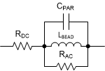 Figure 1-1 Ferrite Bead Equivalent
Circuit
Figure 1-1 Ferrite Bead Equivalent
CircuitNoise in Gate Drive Circuits
In a gate drive circuit, noise on the gate may be caused by a variety of sources including radiated noise and conducted noise from the gate driver's power supply. The most significant source of noise, however, is parasitic oscillation of the power FET's gate due to the parasitics shown in Figure 1-2. The parasitic inductances of the traces and leads of the FET combine with the parasitic capacitances Cgd and Cgs to form an RLC oscillating loop. As the FET begins to turn on, dI/dt can cause ringing across the parasitic inductance which is coupled to the gate of the FET through Cgd. Before the FET has fully turned-on and operates in its linear region, the FET initially passes in the saturation region which has a high gm/gain and is typically undesired for power electronics. During this saturation phase, the FET amplifies oscillations from the gate to the drain which can couple through the FET's Cgd, creating a positive feedback loop.
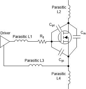 Figure 1-2 Parasitics in a Gate Drive
Circuit
Figure 1-2 Parasitics in a Gate Drive
CircuitThis ringing can be reduced by reducing parasitics through layout optimization, but power FETs inherently have large parasitic capacitance, and it is sometimes hard to reduce parasitic inductance due to other factors at the system level. Two other approaches to solve this issue are to increase the gate resistance, which helps damp the oscillations, or add an extra capacitor from the gate to source, requiring more charge to turn on the FET. While both of these options can be effective in reducing ringing, there is a tradeoff as they both increase the switching time of the FET, limiting drive current in the case of the gate resistor, or increasing the charge needed to turn on the FET in the case of the capacitor. Since switching time is increased, the switching losses also increase, reducing efficiency. This reduction of efficiency emphasizes the need for a way to damp these oscillations without significantly affecting the switching speed and efficiency of the gate drive circuit.
Using Ferrite Beads to Reduce Noise in Gate Drive Circuits
Ferrite beads are most useful in a gate drive application when used to reduce ringing and noise on the gate node of the switch. Traditionally, resistors have been used to reduce this gate noise, but using a resistor lowers the maximum drive current, slowing the switching speed and increasing switching losses. Ferrite beads can be selected to remove noise without significantly reducing peak drive strength, leaving the switching behavior of the power transistor relatively unchanged. The waveforms below show a noisy super junction MOSFET switching without a ferrite bead in Figure 1-3, and with a ferrite bead between the gate and the output in Figure 1-4. Adding the ferrite bead significantly reduced the magnitude of gate oscillations in these figures. Using a ferrite bead on the gate of the power switch is recommended to improve the reliability of the drive circuit, particularly when switching a noisy FET, for example a FET with fast rise time or a low internal gate resistance. Ferrite beads can be used in series with gate resistors to gain the most benefit, as shown in Figure 1-5, and should be placed as close to the FET as possible.
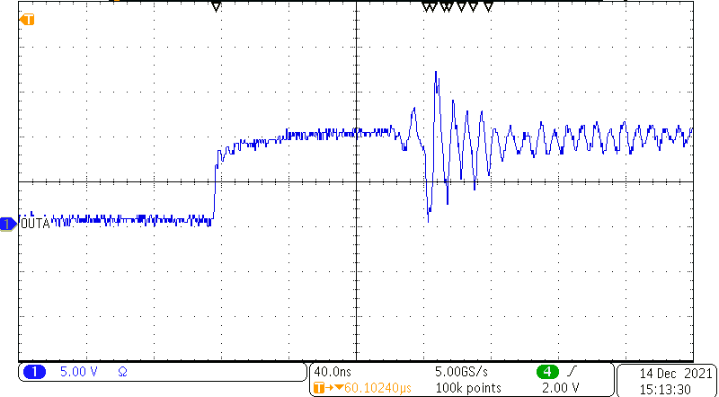 Figure 1-3 Gate Noise Without Ferrite
Bead
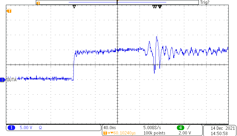 Figure 1-4 Gate Noise With Ferrite
Bead
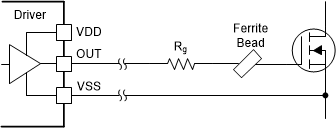 Figure 1-5 Ferrite Bead Placement
It is clear ferrite beads can reduce the noise in a system, but there can be tradeoffs. A common concern with adding components to the gate drive path is reduced switching speed, which leads to reduced efficiency. Figure 1-6 Shows the rising gate signal of a super junction MOSFET switching both with (In blue) and without (In black) a ferrite bead. Looking at the two waveforms, the ferrite bead has minimal effect on normal operation.
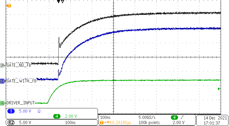 Figure 1-6 Effect of Ferrite Bead on
Normal Switching
Figure 1-6 Effect of Ferrite Bead on
Normal SwitchingSelecting a Ferrite Bead
When selecting a ferrite bead for gate drive applications there are two major factors to take into consideration: the saturation current, and the impedance at the frequencies of interest.
When choosing a ferrite bead it is desirable to have minimum impedance at the driving frequency, and a high impedance at the noise frequency. Generally, the gate oscillation is on the order of 100 MHz but this noise frequency can also be measured in the system to help choose the best ferrite bead. Choosing an appropriate ferrite bead involves looking at the frequency versus impedance plot on the device’s datasheet. This plot should include three lines, the overall impedance (Z), the inductive component of the impedance (X), and the resistive component of the impedance(R). A ferrite bead should be chosen such that the resistive component is maximized at the noise frequency to dissipate as much energy as possible, while the overall impedance at the switching frequency is minimized to prevent unwanted losses. An example plot for the impedance of a ferrite bead is shown in Figure 1-7, based on TDK's MPZ1608 series. The ferrite bead represented by this plot could work for many gate drive applications because it has very low impedance below 1 MHz at the switching frequency, but high impedance starting at 10 MHz and increasing all the way to 300 MHz.
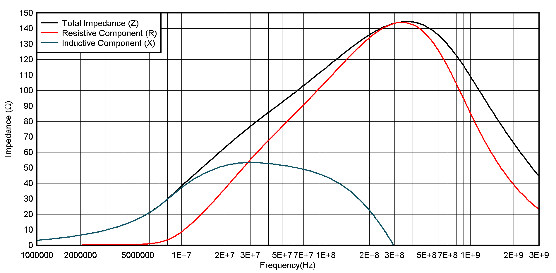 Figure 1-7 Example Ferrite Bead Impedance
Plot
Figure 1-7 Example Ferrite Bead Impedance
PlotThe second factor that must be taken into consideration is the saturation current, the current at which a ferrite bead loses its effectiveness. Ferrite bead performance depends significantly on saturation current, with the attenuation varying well before that rated current is reached. With this in mind it is important to ensure that the impedance remains high enough at peak currents to adequately attenuate noise. This information is not always available in the data sheet, so it may be necessary to request this information from the ferrite bead's manufacturer.
References and Additional Resources
- Texas Instruments, External Gate Resistor Selection Guide
- TDK, MPZ1608 Ferrite Bead data sheet
- Toshiba, Parasitic Oscillation and Ringing of Power MOSFETs