SLYA031A December 2017 – July 2022 INA240
CLASS-D audio amplifiers provide output power with a higher efficiency of over 90% as compared to CLASS-AB amplifiers that can provide an output efficiency of greater than 50%. CLASS-D amplifiers are implemented in portable personal audio systems that provide quality sound output, enabling longer battery life. CLASS-D amplifiers are widely used in automotive systems for E-call systems that provide critical audio feedback to the driver in case of an emergency. In E-call systems, discrete current sensing is often implemented for continuous diagnostics to ensure the speaker is operational at all times.
Current sensing in audio subsystems is widely used in conjunction with CLASS-D amplifiers for diagnostics or to provide speaker current feedback to the DSP for speaker enhancement to emulate SmartAmp systems. The most expensive component in the audio subsystem is the speaker. The impedance of the speakers ranges from 2 Ω for subwoofers to 8 Ω for stereo speakers. Exceeding the current flowing through the speakers has the potential to create excessive heat in the voice coil, which can lead to permanent damage to the speakers.
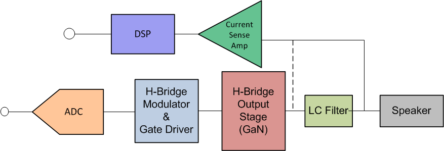
A CLASS-D amplifier subsystem is shown in Figure 1-1. High power, high voltage CLASS-D systems are often built discretely as integrated CLASS-D amplifiers with silicon FETs which have thermal limitations. High voltage CLASS-D systems with GaN FETs are widely accepted due to higher efficiency and the ability to switch at higher frequencies. Integrated CLASS-D amplifiers have integrated overcurrent protection that protects the CLASS-D system and speaker from exceeding current limitations. However, with discrete CLASS-D implementations, discrete current sensors are needed for implementing overcurrent protection to provide diagnostics for speaker protection, making the overall system more reliable.
 Figure 1-1 Discrete CLASS-D System Block Diagram
Current sensing in a CLASS-D system can be realized with either a shunt-based or a magnetic-based system. Shunt-based current sensing is best suited for audio applications because of linearity, lower noise, and higher dynamic range. However, magnetic Hall-effect sensors are lower in cost to implement with drawbacks, such as lower dynamic range, higher noise, and increased output sensitivity to external magnetic fields. Table 1-1 describes a summary of pros and cons when using a shunt-based solution in comparison to a magnetic solution in audio systems.
| Current sensing application | Shunt-Based Current Sense Solution | Magnetic-Based Current Sense Solution | ||
|---|---|---|---|---|
| Pros | Cons | Pros | Cons | |
| Overcurrent protection | Accurate overcurrent protection(<1%) | Series shunt power loss, High series inductance of the shunt | No shunt power loss, No parasitics | Output accuracy is unpredictable due to external magnetic and environmental fields |
| Analog feedback control | High linearity feedback (<0.01%), High dynamic range, Lower noise | Cost of solution | Cost of solution | Lower linearity (>5%), Higher output noise, Lower output range control |
| SmartAmp control | High linearity feedback (<0.01%), High dynamic range, Lower noise, Faster loop control, Faster DSP processing | Cost of solution | Cost of solution | Lower linearity (>5%), Slower control loop response, Longer DSP processing |
Discrete CLASS-D Protection and Diagnostics
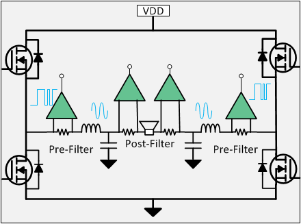
For diagnostics, it is preferable to connect the shunt and the discrete current sense amplifier pre-filter, as shown in Figure 1-2. The challenge with pre-filter current measurement is that the amplifier is subjected to fast switching transients. Amplifiers with high bandwidth and fast output settling are required to measure accurate currents. As the switching frequency increases beyond 150 kHz, the need for unity gain bandwidth of current sense amplifier significantly increases to the order of 15 MHz. Such high-bandwidth amplifiers have the disadvantages of higher Iq, higher offset, and limited output slew rate. However, pre-filter current measurements offer fast response times to overcurrent detection with the ability to provide diagnostics for external LC filtering to detect abnormalities in the passive.
To overcome the challenges of current sensing in pre-filter measurements, a possible cost-effective solution for providing complete diagnostics is to measure currents after the LC filter. After the LC filter, the common mode signal is a slow-moving signal limited to less than 30 kHz. For post-filter current sensing, the current sense amplifier can detect shorted speaker connections and provide information back to the control loop for shutdown, increasing system reliability.
 Figure 1-2 Current Sensing in CLASS-D
Amplifier
Figure 1-2 Current Sensing in CLASS-D
AmplifierSpeaker Parameters Extraction for SmartAmp Implementation
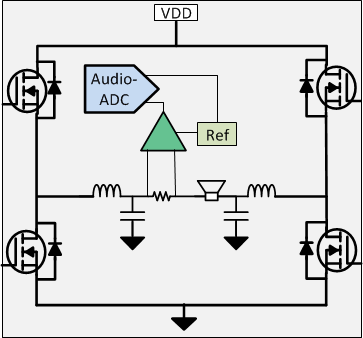
Today, advancements are being made in digital signal processing technology, leading to higher processing power and smaller DSP with lower power consumption. Real-time speaker parameters such as current, voltage, impedance, and temperature are increasingly being measured to create a real-time closed loop speaker system which can adapt to the changes in the environment of the speaker system. One of the key components to realizing a closed loop SmartAmp system is a precision current sense amplifier with high dynamic range, lower noise, and higher bandwidth (greater than 200 kHz). Speaker parameters are measured in the DSP subsystem by measuring current in the feedback system as shown in Figure 1-3.
 Figure 1-3 Closed Loop CLASS-D System With
Current Sensing
Figure 1-3 Closed Loop CLASS-D System With
Current SensingThe INA240 is a high voltage (VCM: -4 V to 80 V), high precision, bidirectional current sense amplifier with low input offset and gain drift across temperature range, making it an ideal device for measuring currents in a CLASS-D subsystem. The INA240 is specifically designed to work in switched-node environments where the common mode transients will have large dv/dt signals. The ability to reject high dv/dt signals enables accurate current measurements with high precision and linearity. With a large dynamic range of 80dB and THD+N of less than 0.04%, the INA240 ensures that the feedback system can correct for nonlinearities. The signal throughput bandwidth of INA240 is 400 kHz with a gain of 20. The high bandwidth of the amplifier enables accurate current measurements with a flat response band up to 200 kHz and benefits in faster signal throughput for overcurrent detection. The INA240 has low maximum input offset voltage of 25 µV and a maximum gain error of 0.2%, allowing for smaller shunt resistance values to be used without sacrificing measurement accuracy.
| Device | Optimized Parameter | Performance Trade-Off |
|---|---|---|
| VCM: -5 V to 110 V, Bandwidth: 1 MHz, Vos: 12 µV | Higher Iq | |
| INA168 | Bandwidth: 800 kHz, Package: SOT-23 | Adjustable gain, External components |
| LMP8601 | VCM: -22 V to 60 V | Offset voltage: 1 mV, Bandwidth: 60 kHz |
| INA253 | VCM: -4 V to 80 V, Integrated low-inductive 2 mΩ, 3 nH shunt |
±15 A |