SWRA758 January 2023 IWR1642 , IWR6443 , IWR6843
1
The IWR6843 mmWave radar device can be used to detect people in a variety of indoor settings. Whether on a factory floor, above elevator doors or in a conference room, the IWR6843 is sensitive enough to detect motions as subtle as the chest expanding and contracting from normal breathing, while selective enough to discern between people and stationary objects.
When designing a radar device for detecting people in an indoor environment, determining the location and angle of the radar is vital for performance. Effective radar designs ensure the radar device’s field of view captures the scene of interest. Depending on the expected room layout, product designers will need to make decisions about their antenna layout, the position of the radar in the room, the angle at which the radar sits within its enclosure and the tuning parameters in the configuration file. Additionally, designing a radar product for a variety of rooms requires some flexibility during installation to allow the radar device to adjust to varying circumstances. This application brief details the best practices TI has developed for placing a radar to detect and track people.
Antenna Layouts
TI’s IWR6843 device offers three transmit antennas and four receiving antennas for a total of 12 virtual antennas. These 12 virtual antennas need to be aligned in the x and y axes on the PCB to discern between objects at different angles. More antennas in the x-axis leads to improved angular resolution in the azimuth angle, and more antennas in the y-axis leads to improved resolution in the elevation angle. TI offers two different antenna layouts for the IWR6843. The ISK antenna layout on the IWR6843ISK EVM is TI’s suggested antenna layout for wall-mounted radars because it offers 8 antennas in the horizontal dimension, maximizing angular resolution in the azimuth. The ODS antenna layout found on both the IWR6843ISK-ODS EVM and IWR6843AOP EVM is TI’s suggested layout for ceiling mounted radars because it offers 4 antennas in the x-axis and 4 antennas in the y-axis, balancing resolution between the azimuth and elevation angles. The main difference between the ODS and AOP devices is that the AOP’s antennas are designed on the device’s package, whereas the ODS’s antennas are etched into the PCB. Developers who need to select an EVM to evaluate with, and eventually an antenna layout to use should use the below steps to make a decision.
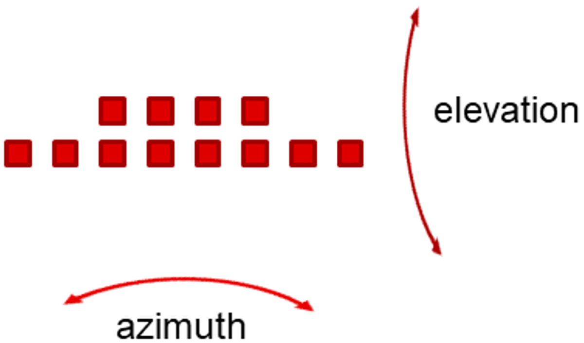 Figure 1-1 ISK Virtual Antenna
Layout
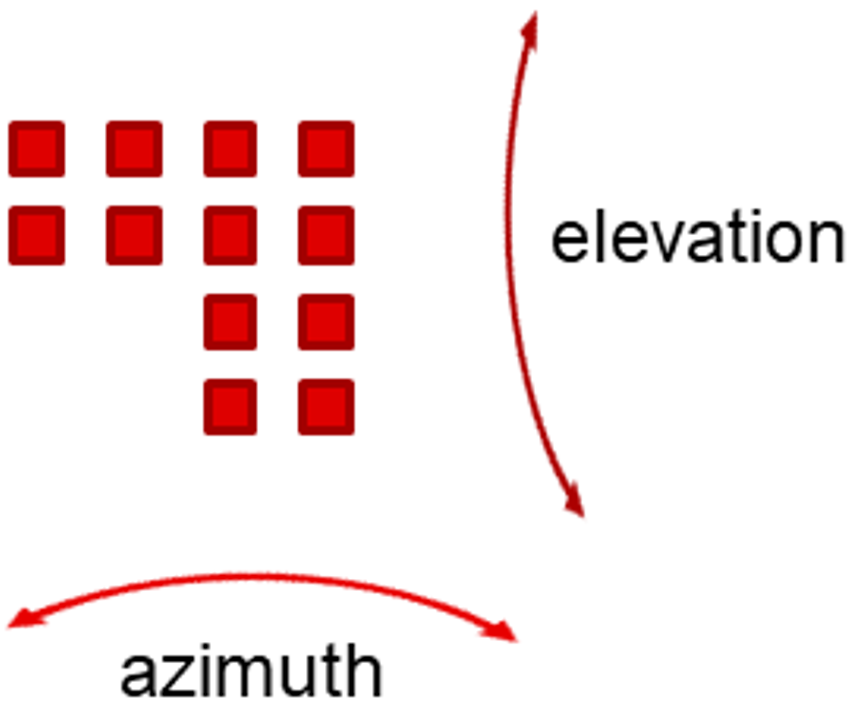 Figure 1-2 ODS/AOP Virtual Antenna
Layout
Figure 1-2 ODS/AOP Virtual Antenna
LayoutProcedure for selecting Antenna Layout
Step 1 – Determine the expected room size and necessary detection area for deployment.
Step 2 – Determine the maximum height at which the device can be mounted
Step 3 – Using the expected device height and the expected room dimensions, determine an appropriate angle of elevation for the radar device to sit at in its enclosure, taking into account the field of view.
Step 4 – Select an antenna layout. A typical angle for the ODS antenna layout is > 20 degrees with the horizontal, and a typical installation for the ISK antenna layout is < 20 degrees with the horizontal.
 Figure 1-3 Radar Angle of Elevation (Side
View)
Figure 1-3 Radar Angle of Elevation (Side
View)For more detailed information about each antenna, see the table below.
| IWRL6432BOOST |
IWR6843AOPEVM |
IWR6843ISK |
IWR68ISK-ODS |
IWR1843BOOST |
IWR1642BOOST |
IWR1443BOOST |
||
|---|---|---|---|---|---|---|---|---|
|
Field of View (FoV) |
Azimuth (degrees) |
+/-60 |
+/-60 |
+/-60 |
+/-60 | +/-60 | +/-60 | +/-60 |
|
Elevation (degrees) |
+/-40 |
+/-60 |
+/-20 |
+/-60 | +/-15 | +/-15 | +/-15 | |
|
Angular Resolution |
Azimuth (degrees) | 19 |
29 |
20 |
29 |
15 |
15 |
15 |
| Elevation (degrees) | 57 |
29 |
58 |
29 |
- |
- |
60 |
|
|
Maximum Distance |
Car (meters) |
* |
87 |
175 |
- |
199 |
199 |
120 |
|
Person (meters) |
* |
49 |
98 |
- |
37 |
37 |
47 |
|
* Maximum distance has not been thoroughly investigated with the IWRL6432 yet.
Additionally, if none of the antennas provided are sufficient for your use case, there exist a large network of third parties that can design an optimal antenna for specific use-cases.
Position and Angle of the Radar Device
The position and angle that the radar device is placed at needs to be considered together, because the optimal angle varies based upon height. TI recommends reviewing height first, as it is more likely to be a limiting factor in indoor environments. It is often best to mount the radar more than 2 meters high. Higher mounts reduce the likelihood of a person obscuring the radar’s field of view by standing directly in front of it. Higher mounts allow for two subsequent possibilities: ceiling mounts or wall mounts.
Ceiling Mounts
If the ceiling is tall enough, then placing the radar on the ceiling ensures there is an unobstructed path between the radar and all the people in the room. Radars should be mounted on the ceiling of a room if the room is tall enough for the radar’s field of view to cover the entire room. Some rooms may be too long, with a ceiling that is too short for the radar’s field of view to pick up the whole room, and in this case, a wall-mounted radar makes more sense. Determining if the ceiling is tall enough can be done with a simple procedure.
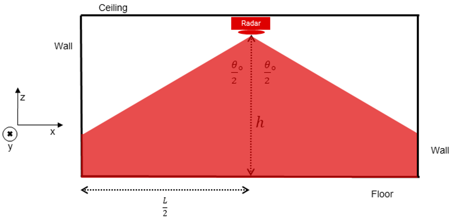 Figure 1-4 Ceiling Mounted Radar
(side-view)
Figure 1-4 Ceiling Mounted Radar
(side-view)For a given ceiling height H, the furthest away a target (assumed to be detectable at 1m tall) can stand and still be in the field of view of the radar is the following :
Let L = longest dimension in the room (likely from 1 corner of the room to the other)
Let θ = field of view of the radar. In the overhead case, it's recommended to use a radar with equal fields of view in both the azimuth and elevation angles.
If the radar is placed on the ceiling, the optimal angle for it to sit in its enclosure is 90 degrees from the horizontal, pointed directly at the floor, as figure 4 shows. The best antenna layout to use in this case is ODS antenna layout, found on both the IWR6843ISK-ODS and IWR6843AOP devices.
Wall Mounts
If the radar cannot be placed on the ceiling at a 90 degree angle with the horizontal, another option is to place it on one of the walls of the room. In this scenario, it is ideal to place the radar in one of the corners of the room, to ensure that the entire room is in the radar’s field of view. If the radar is not placed in the corner, there may be blind spots outside the field of view of the radar in the room as seen in figure 6.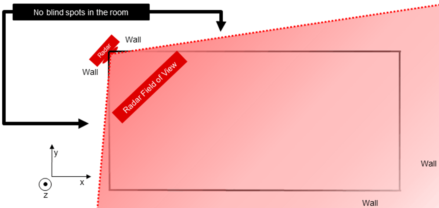 Figure 1-5 Corner Position for Wall Mount
Radar (Viewed from top-down)
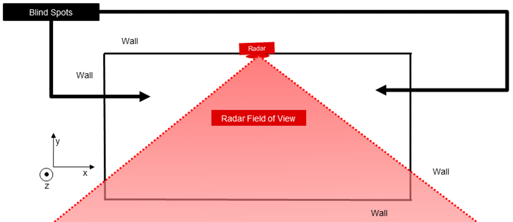 Figure 1-6 Non-Corner Position for Wall
Mount Radar (Viewed from top-down)
Figure 1-6 Non-Corner Position for Wall
Mount Radar (Viewed from top-down)The best height for the wall-mounted radar is still above 2 meters if possible. However, as the radar device gets placed higher, the best angle for it varies based upon the dimensions of the space. The angle that receives the largest amount of power (which corresponds with an increased ability to detect targets) is at azimuth = 0, elevation = 0, which is known as the antenna boresight.
Some product designers often point the boresight to the middle of the room, where people are most likely to be. However, TI recommends pointing the boresight a little bit further forward (align the radar’s boresight angle further to the y-axis).
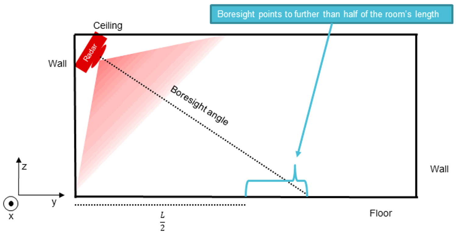 Figure 1-7 Corner Position for Wall
Mount Radar (side-view)
Figure 1-7 Corner Position for Wall
Mount Radar (side-view)Targets directly underneath the radar may be at large angles of elevation from boresight, but since they are at closer range, they will be easier to detect than targets further away at similarly large angles off of boresight. Therefore, angling the radar further forward increases the detection ability further away, without dramatically affecting the detection ability closer to the device. Boresight angles as small as 20-30 degrees below the y-axis can be successful installations depending on the height and room size.
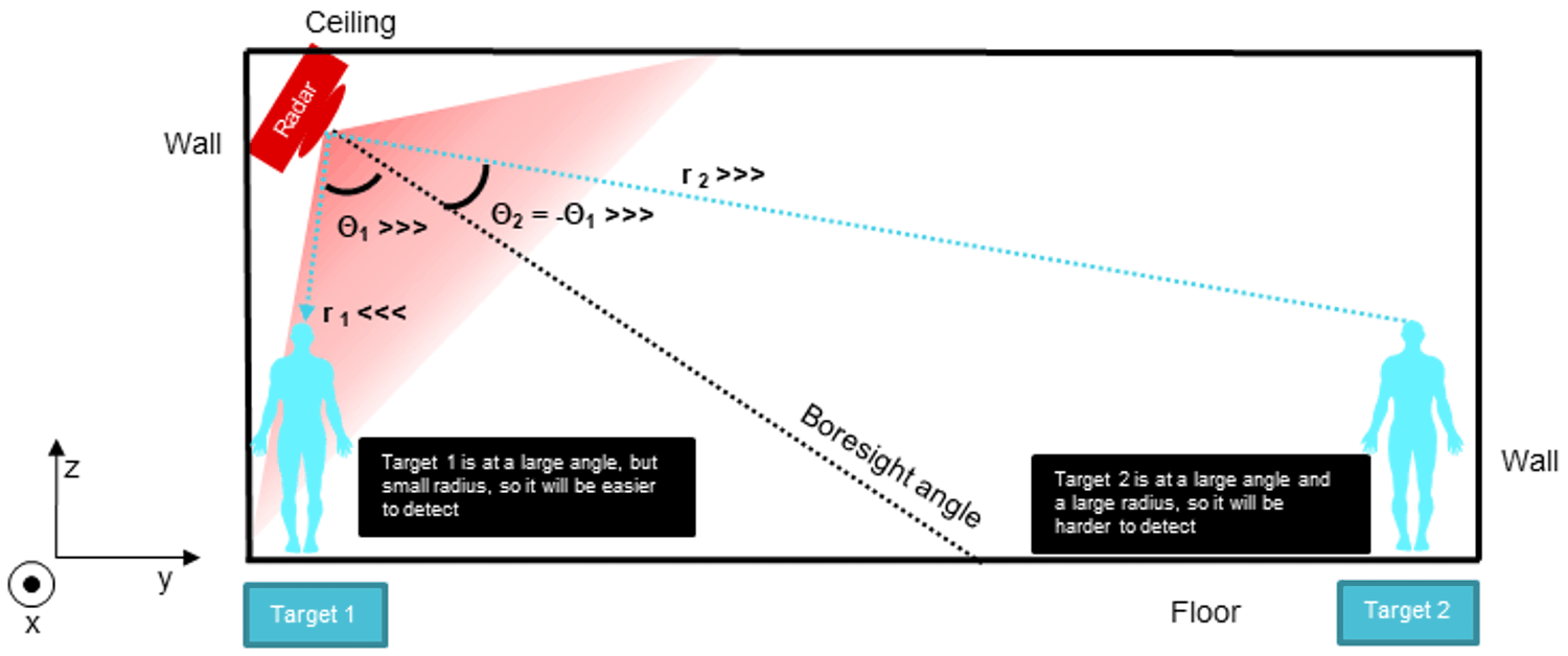 Figure 1-8 People at the same radius,
but different angles of elevation (side-view)
Figure 1-8 People at the same radius,
but different angles of elevation (side-view)Selecting an antenna layout for the wall-mount case will depend on the height and angle of the device. Devices that are mounted higher will need to be pointed further downward, at larger angles with the horizontal, to view the entire scene. As such, they will benefit from the increased resolution in the elevation domain that the ODS antenna layout provides. Scenarios like fall-detection in small rooms would likely perform best with this combination of height, angle and device selection.
Conversely, devices that are mounted lower will need to be pointed further upward, at smaller angles with the horizontal to view the entire scene. Therefore, they will benefit less from elevation information, and should use the ISK antenna layout that gives more information in the azimuth. Scenarios like Automatic Door and Gate sensors would likely maximize their performance with this combination of factors. TI’s typical guidance is to use an ODS antenna layout if the angle to the horizontal is > 20 degrees and to use the ISK antenna layout if the angle is < 20 degrees.
|
Position |
Height |
Angle from the horizontal |
Antenna Design |
Example use-cases |
|
|---|---|---|---|---|---|
|
Overhead Mount |
Middle of the room |
As high as possible |
90 degrees |
ODS or AOP |
- Small conference rooms - Above a bed - Workplace cubicles |
|
Wall Mount (tall mounting height option) |
Corner of the room |
Typically > 2.5 meters |
>20 degrees |
ODS or AOP |
- Larger conference rooms - Open office spaces - Elderly Care Facilities - Short-range security cameras |
| Wall-Mount (short mounting height option) | Corner of the room, or above entry/exit doors | Typically < 2.5 meters | <20 degrees | ISK |
- Larger conference rooms - Automatic doors - Long-range security cameras - Video Doorbells |
Designing for Installation in a Variety of Areas
The spaces that radar devices are installed in can vary greatly in size, shape, obstructions and layout, which requires users to design a flexible product. While a radar device designed for a 4m x 4m room with a 3m ceiling may work perfectly in that environment, it needs to be flexible enough to cover a range of room dimensions and ceiling heights.
One way to design flexibility into a radar device is to allow the radar to set its own boundaries using a perimeter walk for configuration. Using a modified mode of the main binary flashed onto the device, a user could walk the perimeter of the room a few times, letting the radar track them, and then using those track results to dictate the boundaries of the room. The radar could then keep those boundaries and run its normal software. This would let the radar work in a variety of room shapes and sizes without software changes for each device, as well as avoid false triggers from people walking outside the room.
This strategy of using a startup binary that is different from the runtime code as a configuration could be expanded to a number of use-cases to improve performance and simplify installation. The radar device could infer its height through a modified version of level-sensing code. It could determine how much power to broadcast with through its TX Power backoff value. Applications-level parameters could even be tuned too, such as the static detection function provided in the Area Scanner demo, or tracking layer parameters in the People Counting Demo. Overall, adding sensor adaptability in a radar product will help optimize performance in a variety of settings, with only minimal extra work at installation.