JAJSDM7 July 2017 ONET2804TLP
PRODUCTION DATA.
- 1 特長
- 2 アプリケーション
- 3 概要
- 4 改訂履歴
- 5 Pin Configuration and Functions
- 6 Specifications
-
7 Detailed Description
- 7.1 Overview
- 7.2 Functional Block Diagram
- 7.3 Feature Description
- 7.4 Device Functional Modes
- 7.5 Programming
- 7.6
Register Maps
- 7.6.1 Register Descriptions
- 7.6.2 Register 0: Control Settings (address = 00h) [reset = 0h]
- 7.6.3 Register 1: Amplitude and Rate for Channel 1 (address = 01h) [reset = 0h]
- 7.6.4 Register 2: Threshold and Gain for Channel 1 (address = 02h) [reset = 0h]
- 7.6.5 Register 7: Amplitude and Rate for Channel 2 (address = 07h) [reset = 0h]
- 7.6.6 Register 8: Threshold and Gain for Channel 1 (address = 08h) [reset = 0h]
- 7.6.7 Register 13: Amplitude and Rate for Channel 3 (address = 0Dh) [reset = 0h]
- 7.6.8 Register 14: Threshold and Gain for Channel 3 (address = 0Eh) [reset = 0h]
- 7.6.9 Register 19: Amplitude and Rate for Channel 4 (address = 13h) [reset = 0h]
- 7.6.10 Register 20: Threshold and Gain for Channel 4 (address = 14h) [reset = 0h]
- 8 Application and Implementation
- 9 Power Supply Recommendations
- 10Layout
- 11デバイスおよびドキュメントのサポート
- 12メカニカル、パッケージ、および注文情報
1 特長
- 4チャネルのマルチ・レート動作: 最大28Gbps
- 3V電源での消費電力: チャネルごとに90mW
- 差動トランスインピーダンス: 7.5kΩ
- 帯域幅: 17.5GHz
- 入力換算ノイズ: 2μArms
- 入力過負荷電流: 3.2mAPP
- 出力電圧をプログラム可能
- ゲインおよび帯域幅を変更可能
- 各チャネルについての受信信号強度インジケータ(RSSI)
- チャネル間の絶縁(ダイのみ): 40dB
- 単一電源: 2.8V~3.3V
- パッド制御または2線式制御
- オンチップのフィルタ・コンデンサ
- -40℃から+100℃での動作
- ダイ・サイズ: 3250μm×1450μm、チャネル・ピッチ750μm
2 アプリケーション
- 100ギガビット・イーサネットの光レシーバ
- ITU OTL4.4
- 内部リタイミング付きのCFP2、CFP4、QSFP28
3 概要
ONET2804TLPデバイスは、並列光学相互接続用の高ゲインの制限付きトランスインピーダンス・アンプ(TIA)で、データ・レートは最大28Gbpsです。このデバイスは、750μmピッチのフォトダイオード・アレイと組み合わせて、光信号を差動出力電圧へ変換するために使用されます。内部回路によってフォトダイオードの逆バイアス電圧を供給し、各フォトダイオードに供給される平均光電流を検出します。
このデバイスは、ピン制御または2線式シリアル・インターフェイスで使用でき、出力振幅、ゲイン、帯域幅、入力スレッショルドをコントロールできます。
ONET2804TLPは、17.5GHzの帯域幅、7.5kΩのゲイン、入力換算ノイズ2µArms、およびチャネルごとの受信信号強度インジケータ(RSSI)を備えています。40dBのチャネル間絶縁により、レシーバでのクロストーク・ペナルティが低くなります。
このデバイスは単一の2.8V~3.3V電源で動作し、標準消費電流はチャネルごとに90mW、差動出力振幅は300mVPPです。このデバイスは-40℃~+100℃で動作が規定されており、チャネル・ピッチ750μmのダイ形状で供給されます。
製品情報(1)
| 型番 | パッケージ | 本体サイズ(公称) |
|---|---|---|
| ONET2804TLP | ワッフル・パックのベース・ダイ | 3250µm×1450µm |
- 利用可能なすべてのパッケージについては、このデータシートの末尾にある注文情報を参照してください。
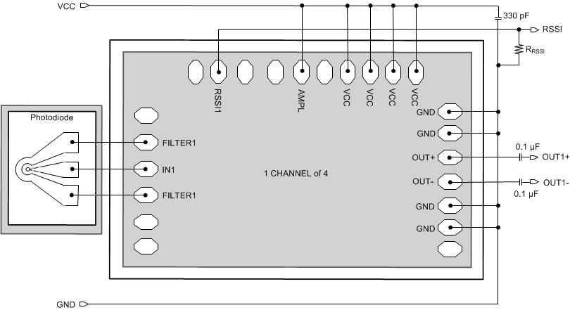
概略回路図

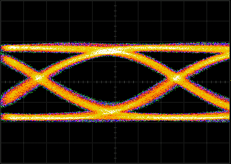
アイ・ダイアグラム
