JAJSCQ6A December   2016  – June 2018 SN65DSI83-Q1

PRODUCTION DATA.  

  1. 特長
  2. アプリケーション
  3. 概要
  4. 改訂履歴
  5. Pin Configuration and Functions
    1.     Pin Functions
  6. Specifications
    1. 6.1 Absolute Maximum Ratings
    2. 6.2 ESD Ratings
    3. 6.3 Recommended Operating Conditions
    4. 6.4 Thermal Information
    5. 6.5 Electrical Characteristics
    6. 6.6 Switching Characteristics
  7. Parameter Measurement Information
  8. Detailed Description
    1. 8.1 Overview
    2. 8.2 Functional Block Diagram
    3. 8.3 Feature Description
      1. 8.3.1 Clock Configurations and Multipliers
      2. 8.3.2 ULPS
      3. 8.3.3 LVDS Pattern Generation
      4. 8.3.4 Reset Implementation
      5. 8.3.5 Initialization Sequence
      6. 8.3.6 LVDS Output Formats
      7. 8.3.7 DSI Lane Merging
      8. 8.3.8 DSI Pixel Stream Packets
      9. 8.3.9 DSI Video Transmission Specifications
    4. 8.4 Programming
      1. 8.4.1 Local I2C Interface Overview
    5. 8.5 Register Maps
      1. 8.5.1 Control and Status Registers Overview
        1. 8.5.1.1 CSR Bit Field Definitions – ID Registers
          1. 8.5.1.1.1 Registers 0x00 – 0x08
            1. Table 4. Registers 0x00 – 0x08 Field Descriptions
        2. 8.5.1.2 CSR Bit Field Definitions – Reset and Clock Registers
          1. 8.5.1.2.1 Register 0x09
            1. Table 5. Register 0x09 Field Descriptions
          2. 8.5.1.2.2 Register 0x0A
            1. Table 6. Register 0x0A Field Descriptions
          3. 8.5.1.2.3 Register 0x0B
            1. Table 7. Register 0x0B Field Descriptions
          4. 8.5.1.2.4 Register 0x0D
            1. Table 8. Register 0x0D Field Descriptions
        3. 8.5.1.3 CSR Bit Field Definitions – DSI Registers
          1. 8.5.1.3.1 Register 0x10
            1. Table 9. Register 0x10 Field Descriptions
          2. 8.5.1.3.2 Register 0x11
            1. Table 10. Register 0x11 Field Descriptions
          3. 8.5.1.3.3 Register 0x12
            1. Table 11. Register 0x12 Field Descriptions
        4. 8.5.1.4 CSR Bit Field Definitions – LVDS Registers
          1. 8.5.1.4.1 Register 0x18
            1. Table 12. Register 0x18 Field Descriptions
          2. 8.5.1.4.2 Register 0x19
            1. Table 13. Register 0x19 Field Descriptions
          3. 8.5.1.4.3 Register 0x1A
            1. Table 14. Register 0x1A Field Descriptions
          4. 8.5.1.4.4 Register 0x1B
            1. Table 15. Register 0x1B Field Descriptions
        5. 8.5.1.5 CSR Bit Field Definitions – Video Registers
          1. 8.5.1.5.1  Register 0x20
            1. Table 16. Register 0x20 Field Descriptions
          2. 8.5.1.5.2  Register 0x21
            1. Table 17. Register 0x21 Field Descriptions
          3. 8.5.1.5.3  Register 0x24
            1. Table 18. Register 0x24 Field Descriptions
          4. 8.5.1.5.4  Register 0x25
            1. Table 19. Register 0x25 Field Descriptions
          5. 8.5.1.5.5  Register 0x28
            1. Table 20. Register 0x28 Field Descriptions
          6. 8.5.1.5.6  Register 0x29
            1. Table 21. Register 0x29 Field Descriptions
          7. 8.5.1.5.7  Register 0x2C
            1. Table 22. Register 0x2C Field Descriptions
          8. 8.5.1.5.8  Register 0x2D
            1. Table 23. Register 0x2D Field Descriptions
          9. 8.5.1.5.9  Register 0x30
            1. Table 24. Register 0x30 Field Descriptions
          10. 8.5.1.5.10 Register 0x31
            1. Table 25. Register 0x31 Field Descriptions
          11. 8.5.1.5.11 Register 0x34
            1. Table 26. Register 0x34 Field Descriptions
          12. 8.5.1.5.12 Register 0x36
            1. Table 27. Register 0x36 Field Descriptions
          13. 8.5.1.5.13 Register 0x38
            1. Table 28. Register 0x38 Field Descriptions
          14. 8.5.1.5.14 Register 0x3A
            1. Table 29. Register 0x3A Field Descriptions
          15. 8.5.1.5.15 Register 0x3C
            1. Table 30. Register 0x3C Field Descriptions
        6. 8.5.1.6 CSR Bit Field Definitions – IRQ Registers
          1. 8.5.1.6.1 Register 0xE0
            1. Table 31. Register 0xE0 Field Descriptions
          2. 8.5.1.6.2 Register 0xE1
            1. Table 32. Register 0xE1 Field Descriptions
          3. 8.5.1.6.3 Register 0xE5
            1. Table 33. Register 0xE5 Field Descriptions
  9. Application and Implementation
    1. 9.1 Application Information
      1. 9.1.1 Video STOP and Restart Sequence
      2. 9.1.2 Reverse LVDS Pin Order Option
      3. 9.1.3 IRQ Usage
    2. 9.2 Typical Application
      1. 9.2.1 Design Requirements
      2. 9.2.2 Detailed Design Procedure
        1. 9.2.2.1 Example Script
      3. 9.2.3 Application Curve
  10. 10Power Supply Recommendations
    1. 10.1 VCC Power Supply
    2. 10.2 VCORE Power Supply
  11. 11Layout
    1. 11.1 Layout Guidelines
      1. 11.1.1 Package Specific
      2. 11.1.2 Differential Pairs
      3. 11.1.3 Ground
    2. 11.2 Layout Example
  12. 12デバイスおよびドキュメントのサポート
    1. 12.1 ドキュメントのサポート
      1. 12.1.1 関連資料
    2. 12.2 ドキュメントの更新通知を受け取る方法
    3. 12.3 コミュニティ・リソース
    4. 12.4 商標
    5. 12.5 静電気放電に関する注意事項
    6. 12.6 Glossary
  13. 13メカニカル、パッケージ、および注文情報

パッケージ・オプション

メカニカル・データ(パッケージ|ピン)
サーマルパッド・メカニカル・データ
発注情報

特長

  • 車載アプリケーションに対応
  • 下記内容でAEC-Q100認定済み:
    • デバイス温度グレード2: 動作時周囲温度–40℃~+105℃
    • デバイスHBM ESD分類レベル3A
    • デバイスCDM ESD分類レベルC6
  • MIPI® D-PHYバージョン1.00.00物理レイヤ・フロントエンドおよびDisplay Serial Interface (DSI)バージョン1.02.00を実装
  • シングル・チャネルDSIレシーバは、チャネルごとに1、2、3、4本のD-PHYデータ・レーンとして構成でき、レーンごとに最高1Gbpsで動作
  • 18bppおよび24bppのDSIビデオ・パケットをRGB666およびRGB888フォーマットでサポート
  • 最大解像度: 60fps WUXGA 1920×1200、18bppおよび24bppカラー(低ブランキング)。60fps、1366×768/1280×800 (18bppおよび24bpp)のディスプレイにも適切
  • シングル・リンクLVDS用出力
  • シングル・チャネルDSIからシングル・リンクLVDSへの動作モードをサポート
  • LVDS出力クロック範囲: 25MHz~154MHz
  • LVDSピクセル・クロックはフリーランニングの連続D-PHYクロックまたは外部リファレンス・クロック(REFCLK)により供給
  • 1.8VのメインVCC電源
  • 低消費電力機能として、SHUTDOWNモード、低減LVDS出力電圧スイング、同相、MIPI超低消費電力状態(ULPS)をサポート
  • PCB配線を簡素化するため、LVDSチャネルSWAPおよびLVDS PIN順序の反転機能を搭載
  • 64ピンの10mm×10mm HTQFP (PAP) PowerPAD™ ICパッケージで供給
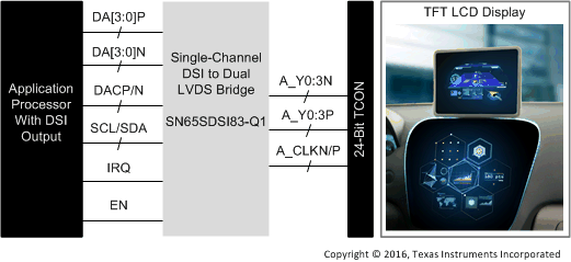
  • SN65DSI83-Q1回路図

    SN65DSI83-Q1 alt_sllsew7.gif