SNOSC48O June 2000 – December 2014 LM2936
PRODUCTION DATA.
8 Application and Implementation
NOTE
Information in the following applications sections is not part of the TI component specification, and TI does not warrant its accuracy or completeness. TI’s customers are responsible for determining suitability of components for their purposes. Customers should validate and test their design implementation to confirm system functionality.
8.1 Application Information
The LM2936 ultra-low quiescent current regulator features low dropout voltage and low current in the standby mode. The LM2936 has a 40-V maximum operating voltage limit, a −40°C to 125°C operating temperature range, –24-V input voltage protection and ±3% output voltage tolerance over the entire output current, input voltage, and temperature range This following section presents a simplified discussion of the design process. Also the WEBENCH® software may be used to generate complete designs. When generating a design, WEBENCH utilizes iterative design procedure and accesses comprehensive databases of components. Please go to www.ti.com for more details.
8.2 Typical Application
Figure 21 shows the typical application circuit for the LM2936. For the LM2936 5-V option, the output capacitor, COUT, must have a capacitance value of at least 10 µF with an equivalent series resistance (ESR) of at least 300 mΩ, but no more than 8 Ω. For the LM2936 3.3-V and 3-V options, the output capacitor, COUT, must have a capacitance value of at least 22 µF with an ESR of at least 300 mΩ, but no more than 8 Ω. The minimum capacitance value and the ESR requirements apply across the entire expected operating ambient temperature range.
8.2.1 Design Requirements
Table 1. Design Parameters
| DESIGN PARAMETER | EXAMPLE VALUE |
|---|---|
| Output voltage | 5 V |
| Input voltage | 10 V to 26 V |
| Output current requirement | 1 mA to 50 mA |
| Input capacitor | 0.1 µF |
| Output capacitance | 10 µF minimum |
| Output capacitor ESR value | 300 mΩ to 8 Ω |
8.2.2 Detailed Design Procedure
8.2.2.1 External Capacitors
The output capacitor is critical to maintaining regulator stability, and must meet the required conditions for both ESR and minimum amount of capacitance.
8.2.2.1.1 Minimum Capacitance
The minimum output capacitance required to maintain stability is at least 10 µF for the LM2936 5-V option, and at least 22 µF for the 3.3-V and 3-V options. This value may be increased without limit. Larger values of output capacitance will give improved transient response.
8.2.2.1.2 ESR Limits
The ESR of the output capacitor will cause loop instability if it is too high, or too low. ESR, of the COUT capacitor must at least 300 mΩ, but no more than 8 Ω.
8.2.2.2 Output Capacitor ESR
It is essential that the output capacitor meet the capacitance and ESR requirements, or oscillations can result. The ESR is used with the output capacitance in
Ceramic capacitors (MLCC) can be used for COUT only if a series resistor is added to simulate the ESR requirement. The ESR is not optional, it is mandatory. Typically, a 500-mΩ to 1-Ω series resistor is used for this purpose. When using ceramic capacitors, due diligence must be given to initial tolerances, capacitance derating due to applied DC voltage, and capacitance variations due to temperature. Dielectric types X5R and X7R are preferred.
8.2.3 Application Curve
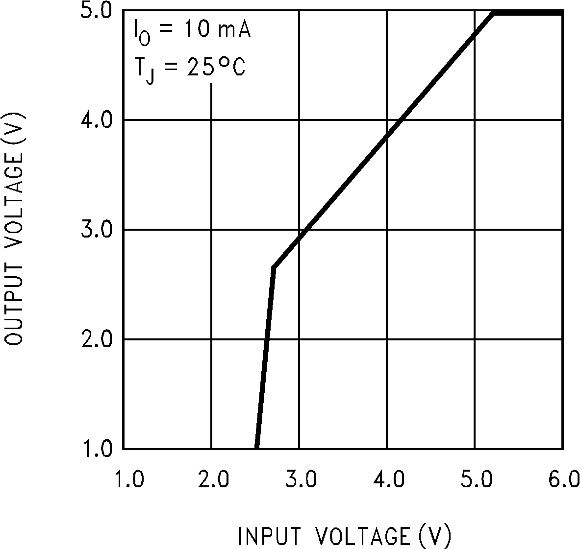 Figure 22. LM2936 VOUT vs. VIN