JAJS924J June 1999 – November 2016 LM61
PRODUCTION DATA.
- 1 特長
- 2 アプリケーション
- 3 概要
- 4 改訂履歴
- 5 Pin Configuration and Functions
- 6 Specifications
- 7 Detailed Description
- 8 Application and Implementation
- 9 Power Supply Recommendations
- 10Layout
- 11デバイスおよびドキュメントのサポート
- 12メカニカル、パッケージ、および注文情報
パッケージ・オプション
メカニカル・データ(パッケージ|ピン)
サーマルパッド・メカニカル・データ
発注情報
8 Application and Implementation
NOTE
Information in the following applications sections is not part of the TI component specification, and TI does not warrant its accuracy or completeness. TI’s customers are responsible for determining suitability of components for their purposes. Customers should validate and test their design implementation to confirm system functionality.
8.1 Application Information
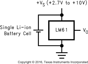
The LM61 has a wide supply range and a 10-mV/°C output slope with a 600-mV DC. Therefore, it can be easily applied in many temperature-sensing applications where a single supply is required for positive and negative temperatures.
8.2 Typical Applications
8.2.1 Typical Temperature Sensing Circuit

8.2.1.1 Design Requirements
For this design example, use the parameters listed in Table 1 as the input parameters.
Table 1. Design Parameters
| PARAMETER | VALUE |
|---|---|
| Power supply voltage | 2.7 V to 3.3 V |
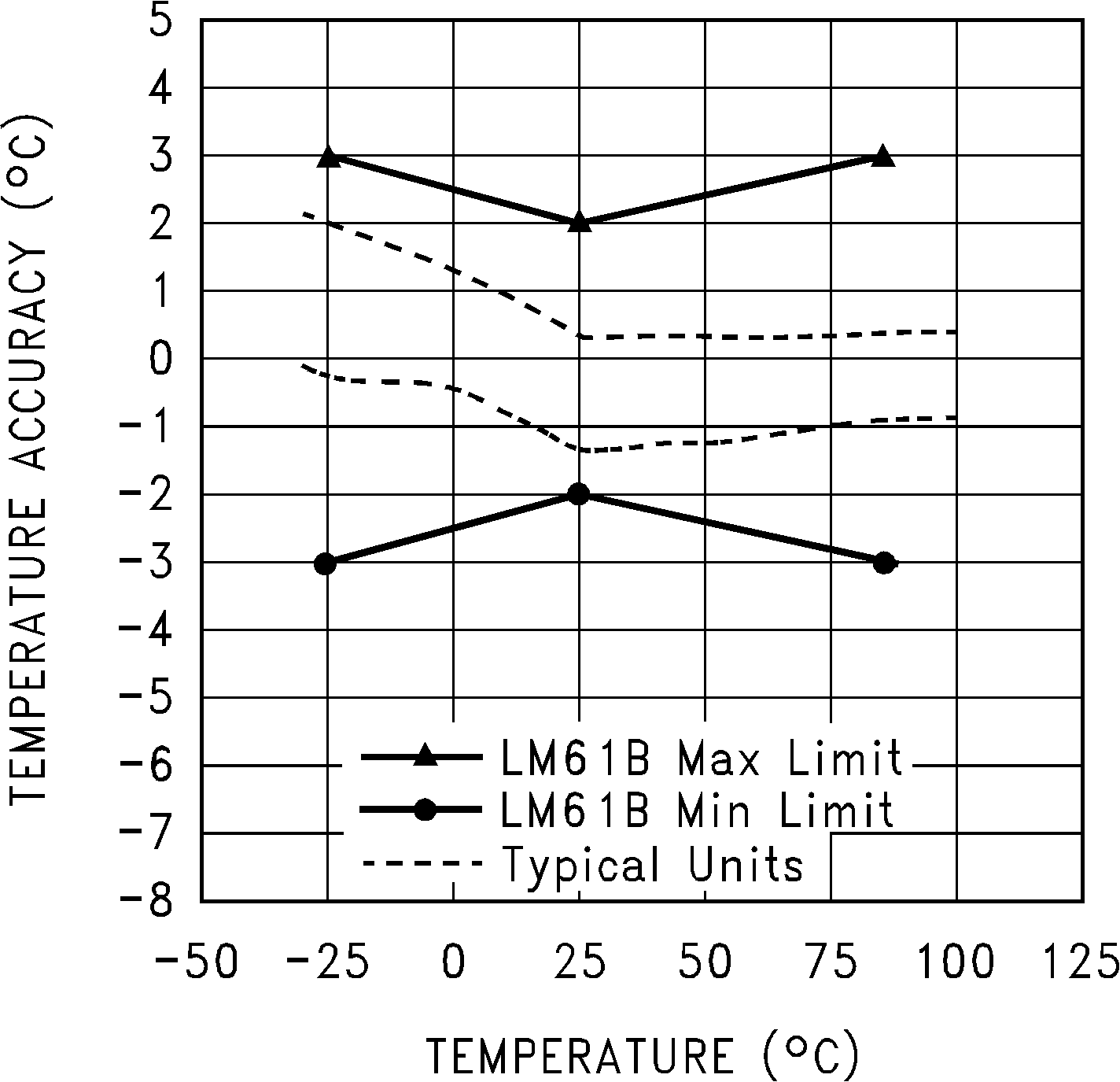
| Accuracy at 25°C | ±2°C (maximum) |
| Accuracy over –25°C to 85°C | ±3°C (maximum) |
| Temperature slope | 10 mV/°C |
8.2.1.2 Detailed Design Procedure
The LM61 is a simple temperature sensor that provides an analog output. Therefore, design requirements related to layout outweigh other requirements in importance. See Layout for more information.
8.2.1.2.1 Capacitive Loads
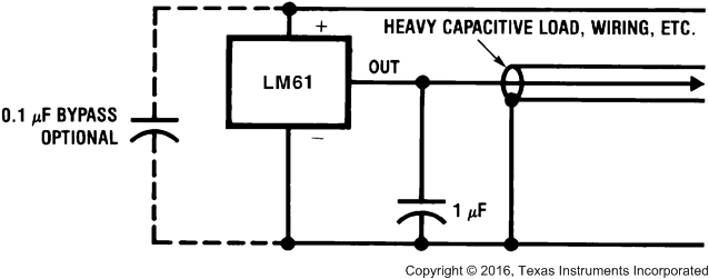
The LM61 handles capacitive loading well. Without any special precautions, the LM61 can drive any capacitive load as shown in Figure 12. Over the specified temperature range the LM61 has a maximum output impedance of 5 kΩ. In an extremely noisy environment it may be necessary to add some filtering to minimize noise pickup. It is recommended that 0.1-µF capacitor be added between +VS and GND to bypass the power-supply voltage, as shown in Figure 13. In a noisy environment it may be necessary to add a capacitor from VOUT to ground. A 1-µF output capacitor with the 5-kΩ maximum output impedance forms a 32-Hz lowpass filter. Because the thermal time constant of the LM61 is much slower than the 5-ms time constant formed by the RC, the overall response time of the LM61 is not significantly affected. For much larger capacitors this additional time lag increases the overall response time of the LM61.
 Figure 12. LM61 No Decoupling Required for Capacitive Load
 Figure 13. LM61 with Filter for Noisy Environments
8.2.1.3 Application Curve
 Figure 14. Accuracy vs Temperature
8.2.2 Other Application Circuits
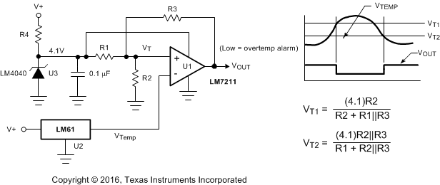
Figure 15 shows an application circuit example using the LM61 device. Customers must fully validate and test any circuit before implementing a design based on an example in this section. Unless otherwise noted, the design procedures in Typical Temperature Sensing Circuit are applicable.
 Figure 15. Centigrade Thermostat
 Figure 16. Conserving Power Dissipation with Shutdown