SNAS647D February 2015 – March 2016 TDC7200
PRODUCTION DATA.
- 1 Features
- 2 Applications
- 3 Description
- 4 Revision History
- 5 Companion Device
- 6 Pin Configuration and Functions
- 7 Specifications
-
8 Detailed Description
- 8.1 Overview
- 8.2 Functional Block Diagram
- 8.3 Feature Description
- 8.4 Device Functional Modes
- 8.5 Programming
- 8.6
Register Maps
- 8.6.1 Register Initialization
- 8.6.2 CONFIG1: Configuration Register 1 R/W (address = 00h) [reset = 0h]
- 8.6.3 CONFIG2: Configuration Register 2 R/W (address = 01h) [reset = 40h]
- 8.6.4 INT_STATUS: Interrupt Status Register (address = 02h) [reset = 00h]
- 8.6.5 INT_MASK: Interrupt Mask Register R/W (address = 03h) [reset = 07h]
- 8.6.6 COARSE_CNTR_OVF_H: Coarse Counter Overflow High Value Register (address = 04h) [reset = FFh]
- 8.6.7 COARSE_CNTR_OVF_L: Coarse Counter Overflow Low Value Register (address = 05h) [reset = FFh ]
- 8.6.8 CLOCK_CNTR_OVF_H: Clock Counter Overflow High Register (address = 06h) [reset = FFh]
- 8.6.9 CLOCK_CNTR_OVF_L: Clock Counter Overflow Low Register (address = 07h) [reset = FFh]
- 8.6.10 CLOCK_CNTR_STOP_MASK_H: CLOCK Counter STOP Mask High Value Register (address = 08h) [reset = 00h]
- 8.6.11 CLOCK_CNTR_STOP_MASK_L: CLOCK Counter STOP Mask Low Value Register (address = 09h) [reset = 00h]
- 8.6.12 TIME1: Time 1 Register (address: 10h) [reset = 00_0000h]
- 8.6.13 CLOCK_COUNT1: Clock Count Register (address: 11h) [reset = 00_0000h]
- 8.6.14 TIME2: Time 2 Register (address: 12h) [reset = 00_0000h]
- 8.6.15 CLOCK_COUNT2: Clock Count Register (address: 13h) [reset = 00_0000h]
- 8.6.16 TIME3: Time 3 Register (address: 14h) [reset = 00_0000h]
- 8.6.17 CLOCK_COUNT3: Clock Count Registers (address: 15h) [reset = 00_0000h]
- 8.6.18 TIME4: Time 4 Register (address: 16h) [reset = 00_0000h]
- 8.6.19 CLOCK_COUNT4: Clock Count Register (address: 17h) [reset = 00_0000h]
- 8.6.20 TIME5: Time 5 Register (address: 18h) [reset = 00_0000h]
- 8.6.21 CLOCK_COUNT5: Clock Count Register (address: 19h) [reset = 00_0000h]
- 8.6.22 TIME6: Time 6 Register (address: 1Ah) [reset = 00_0000h]
- 8.6.23 CALIBRATION1: Calibration 1 Register (address: 1Bh ) [reset = 00_0000h]
- 8.6.24 CALIBRATION2: Calibration 2 Register (address: 1Ch ) [reset = 00_0000h]
- 9 Application and Implementation
- 10Power Supply Recommendations
- 11Layout
- 12Device and Documentation Support
- 13Mechanical, Packaging, and Orderable Information
パッケージ・オプション
メカニカル・データ(パッケージ|ピン)
- PW|14
サーマルパッド・メカニカル・データ
- PW|14
発注情報
1 Features
- Resolution: 55 ps
- Standard Deviation: 35 ps
- Measurement Range:
- Mode 1: 12 ns to 500 ns
- Mode 2: 250 ns to 8 ms
- Low Power Consumption: 0.5 µA (2 SPS)
- Supports up to 5 STOP Signals
- Autonomous Multi-Cycle Averaging Mode for Low Power Consumption
- Supply Voltage: 2 V to 3.6 V
- Operating Temperature –40°C to 85°C
- SPI Host Interface for Configuration and Register Access
2 Applications
3 Description
The TDC7200 is a Time-to-Digital Converter (TDC) for ultrasonic sensing measurements such as water flow meter, gas flow meter, and heat flow meter. When paired with the TDC1000 (ultrasonic analog-front-end), the TDC7200 can be a part of a complete TI ultrasonic sensing solution that includes the MSP430, power, wireless, and source code.
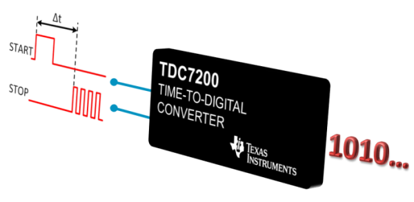
The Time to Digital Converter (TDC) performs the function of a stopwatch and measures the elapsed time (time-of-flight or TOF) between a START pulse and up to five STOP pulses. The ability to measure from START to multiple STOPs gives users the flexibility to select which STOP pulse yields the best echo performance.
The device has an internal self-calibrated time base which compensates for drift over time and temperature. Self-calibration enables time-to-digital conversion accuracy in the order of picoseconds. This accuracy makes the TDC7200 ideal for flow meter applications, where zero and low flow measurements require high accuracy.
When placed in the Autonomous Multi-Cycle Averaging Mode, the TDC7200 can be optimized for low system power consumption, making it ideal for battery powered flow meters. In this mode, the host can go to sleep to save power, and it can wake up when interrupted by the TDC upon completion of the measurement sequence.
Device Information(1)
| PART NUMBER | PACKAGE | BODY SIZE (NOM) |
|---|---|---|
| TDC7200 | TSSOP (14) | 5.00 mm × 4.40 mm |
- For all available packages, see the orderable addendum at the end of the data sheet.
