SBFS031F February 2006 – September 2016 DIX4192
PRODUCTION DATA.
- 1 Features
- 2 Applications
- 3 Description
- 4 Revision History
- 5 Description (continued)
- 6 Device Comparison Table
- 7 Pin Configuration and Functions
- 8 Specifications
-
9 Detailed Description
- 9.1 Overview
- 9.2 Functional Block Diagram
- 9.3
Feature Description
- 9.3.1 RESET Operation
- 9.3.2 Master and Reference Clocks
- 9.3.3 Audio Serial Port Operation
- 9.3.4 Overview of the AES3 Digital Audio Interface Protocol
- 9.3.5 Digital Interface Transmitter (DIT) Operation
- 9.3.6 Digital Interface Receiver (DIR) Operation
- 9.3.7 General-Purpose Digital Outputs
- 9.3.8 Interrupt Output
- 9.4 Device Functional Modes
- 9.5 Register Maps
- 10Application and Implementation
- 11Power Supply Recommendations
- 12Layout
- 13Device and Documentation Support
- 14Mechanical, Packaging, and Orderable Information
Package Options
Mechanical Data (Package|Pins)
- PFB|48
Thermal pad, mechanical data (Package|Pins)
- PFB|48
Orderable Information
1 Features
- Digital Audio Interface Transmitter (DIT)
- Supports Sampling Rates Up to 216 kHz
- Includes Differential Line Driver and
CMOS-Buffered Outputs
- Digital Audio Interface Receiver (DIR)
- PLL Lock Range Includes Sampling Rates from 20 kHz to 216 kHz
- Four Differential-Input Line Receivers and an Input Multiplexer
- Bypass Multiplexer Routes Line Receiver Outputs to Line Driver and Buffer Outputs
- Automatic Detection of Non-PCM Audio Streams (DTS CD/LD and IEC 61937 formats)
- Audio CD Q-Channel Sub-Code Decoding and Data Buffer
- Low Jitter Recovered Clock Output
- User-Selectable Serial Host Interface: SPI™ or I2C
- Provides Access to On-Chip Registers and Data Buffers
- Status Registers and Interrupt Generation for Flag and Error Conditions
- Block-Sized Data Buffers for Both Channel Status and User Data
- Two Audio Serial Ports (Ports A and B)
- Synchronous Serial Interface to External Signal Processors, Data Converters, and Logic
- Slave or Master Mode Operation With Sampling Rates Up to 216 kHz
- Supports Left-Justified, Right-Justified, and Philips I2S™ Data Formats
- Supports Audio Data Word Lengths Up to
24 Bits
- Four General-Purpose Digital Outputs
- Multifunction Programmable Through Control Registers
- Extensive Power-Down Support
- Functional Blocks May Be Disabled Individually When Not In Use
- Operates From 1.8-V Core and 3.3-V I/O Power Supplies
- Small TQFP-48 Package, Compatible With the SRC4382 and SRC4392
2 Applications
- Digital Audio Recorders and Mixing Desks
- Digital Audio Interfaces for Computers
- Digital Audio Routers and Distribution Systems
- Broadcast Studio Equipment
- DVD and CD Recorders
- Surround Sound Decoders and A/V Receivers
- Car Audio Systems
3 Description
The DIX4192 device is a highly-integrated CMOS device designed for use in professional and broadcast digital audio systems. The DIX4192 combines a digital audio interface receiver (DIR) and transmitter (DIT), two audio serial ports, and flexible distribution logic for interconnection of the function block data and clocks.
The DIR and DIT are compatible with the AES3, S/PDIF, IEC 60958, and EIAJ CP-1201 interface standards. The audio serial ports and DIT may be operated at sampling rates up to 216 kHz. The DIR lock range includes sampling rates from 20 kHz to 216 kHz.
Device Information(1)
| PART NUMBER | PACKAGE | BODY SIZE (NOM) |
|---|---|---|
| DIX4192 | TQFP (48) | 7.00 mm × 7.00 mm |
- For all available packages, see the orderable addendum at the end of the data sheet.
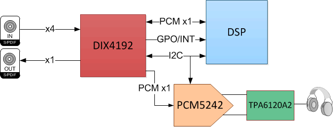
DIX4192 Typical Application

4 Revision History
Changes from E Revision (April 2016) to F Revision
- Changed fMCLK Max value From: 2.27 To: 27.7 Go
Changes from D Revision (January 2016) to E Revision
- Changed "IIH High-level input current" MAX value From: 10 µA To: 25 µA in the Electrical Characteristics tableGo
- Changed Byte 2 in Figure 22a) Current Address Read, .. Go
Changes from C Revision (June 2006) to D Revision
- Added ESD Ratings table, Feature Description section, Device Functional Modes section, Application and Implementation section, Power Supply Recommendations section, Layout section, Device and Documentation Support section, and Mechanical, Packaging, and Orderable Information section. Go