JAJSBH7C June 2011 – October 2016
PRODUCTION DATA.
- 1 特長
- 2 アプリケーション
- 3 概要
- 4 改訂履歴
- 5 Pin Configuration and Functions
- 6 Specifications
-
7 Detailed Description
- 7.1 Overview
- 7.2 Functional Block Diagram
- 7.3
Feature Description
- 7.3.1
Analog-to-Digital Conversion (ADC)
- 7.3.1.1 General Features
- 7.3.1.2 3-to-6 Series Cell Configuration
- 7.3.1.3 Cell Voltage Measurements
- 7.3.1.4 GPAI or VBAT Measurements
- 7.3.1.5 Temperature Measurement
- 7.3.1.6 ADC Band-Gap Voltage Reference
- 7.3.1.7 Conversion Control
- 7.3.1.8 Secondary Protection
- 7.3.1.9 Cell Overvoltage Fault Detection (COV)
- 7.3.1.10 Cell Undervoltage Fault Detection (CUV)
- 7.3.1.11 Overtemperature Detection
- 7.3.1.12 Fault and Alert Behavior
- 7.3.1.13 Secondary Protector Built-In Self-Test Features
- 7.3.2 Cell Balancing
- 7.3.3 Other Features and Functions
- 7.3.4 Communications
- 7.3.5 Device-to-Device Vertical Bus (VBUS) Interface
- 7.3.6 Packet Formats
- 7.3.7 Device Addressing
- 7.3.8 Changes and Enhancements for bq76PL536A
- 7.3.1
Analog-to-Digital Conversion (ADC)
- 7.4 Device Functional Modes
- 7.5 Programming
- 7.6
Register Maps
- 7.6.1 I/O Register Details
- 7.6.2 Register Types
- 7.6.3 Register Details
- 7.6.4 GPAI (0x01, 0x02) Register
- 7.6.5 VCELLn Register (0x03…0x0e)
- 7.6.6 TEMPERATURE1 Register (0x0f, 0x10)
- 7.6.7 TEMPERATURE2 Register (0x11, 0x12)
- 7.6.8 ALERT_STATUS Register (0x20)
- 7.6.9 FAULT_STATUS Register (0x21)
- 7.6.10 COV_FAULT Register (0x22)
- 7.6.11 CUV_FAULT Register (0x23)
- 7.6.12 PARITY_H Register (0x24) (PRESULT_A (R/O))
- 7.6.13 PARITY_H Register (0x25) (PRESULT_B (R/O))
- 7.6.14 ADC_CONTROL Register (0x30)
- 7.6.15 IO_CONTROL Register (0x31)
- 7.6.16 CB_CTRL Register (0x32)
- 7.6.17 CB_TIME Register (0x33)
- 7.6.18 ADC_CONVERT Register (0x34)
- 7.6.19 SHDW_CTRL Register (0x3a)
- 7.6.20 ADDRESS_CONTROL Register (0x3b)
- 7.6.21 RESET Register (0x3c)
- 7.6.22 TEST_SELECT Register (0x3d)
- 7.6.23 E_EN Register (0x3f)
- 7.6.24 FUNCTION_CONFIG Register (0x40)
- 7.6.25 IO_CONFIG Register (0x41)
- 7.6.26 CONFIG_COV Register (0x42)
- 7.6.27 CONFIG_COVT Register (0x43)
- 7.6.28 CONFIG_UV Register (0x44)
- 7.6.29 CONFIG_CUVT Register (0x45)
- 7.6.30 CONFIG_OT Register (0x46)
- 7.6.31 CONFIG_OTT Register (0x47)
- 7.6.32 USERx Register (0x48-0x4b) (USER1-4)
- 8 Application and Implementation
- 9 Power Supply Recommendations
- 10Layout
- 11デバイスおよびドキュメントのサポート
- 12メカニカル、パッケージ、および注文情報
パッケージ・オプション
メカニカル・データ(パッケージ|ピン)
- PAP|64
サーマルパッド・メカニカル・データ
- PAP|64
発注情報
1 特長
- 3~6個の直列セルのサポート、すべての化学方式に対応
- ホットプラグ可能
- データ通信用の高速シリアル・ペリフェラル・インターフェイス(SPI)
- スタック可能な垂直インターフェイス
- デバイス間の絶縁部品が不要
- 工業用温度範囲: -40℃~85℃
- 高精度のA/Dコンバータ(ADC)
- 標準精度±1mV
- 14ビット分解能、変換時間6µs
- 9つのADC入力: 6つのセル電圧、1つの6セル・ブリック電圧、2つの温度、1つの汎用入力
- 測定同期の専用ピン
- 構成データをECC (Error Check/Correct)付きOTP (One-Time-Programmable)レジスタに保存
- 次の用途に使用可能な組み込みコンパレータ(2次保護)
- 過電圧および低電圧保護
- 過熱保護
- プログラム可能なスレッショルドおよび遅延時間
- 専用のフォルト出力信号
- 安全性タイムアウト機能付きのセル・バランス制御出力
- 外部部品によってバランス電流を設定
- 電源電圧範囲: 連続6V~30V、ピーク36V
- 低消費電力
- スリープ時12µA、アイドル時45µA (標準値)
- 高精度の5V、3mA LDOを搭載
2 アプリケーション
- 無停電電源(UPS)
- 電動自転車、電動スクーター
- 大型バッテリ・システム
3 概要
bq76PL536Aデバイスは、直列に接続された3~6個のリチウムイオン・セル用の、スタック可能なバッテリ・モニタおよびプロテクタです。bq76PL536Aにはアナログ・フロント・エンド(AFE)とともに、高精度のA/Dコンバータ(ADC)が内蔵されており、バッテリ・セルの正確な電圧測定に使用されます。温度測定用には、独立のADCが使用されます。
温度測定に加えて、保護のために過電圧および低電圧もチャネルごとに監視されます。保護スレッショルドと遅延時間はユーザーがプログラム可能で、これらの値は不揮発性メモリに保存されます。これらのスレッショルドのいずれかを超過した場合、FAULT出力により通知されます。
スタックされたbq76PL536Aデバイスにより、192セルのセル・スタックをサポート可能です。すべてのデバイスは、高速のSPIインターフェイスにより接続されます。
製品情報(1)
| 型番 | パッケージ | 本体サイズ(公称) |
|---|---|---|
| bq76PL536A | HTQFP (64) | 10.00mm×10.00mm |
- 提供されているすべてのパッケージについては、巻末の注文情報を参照してください。
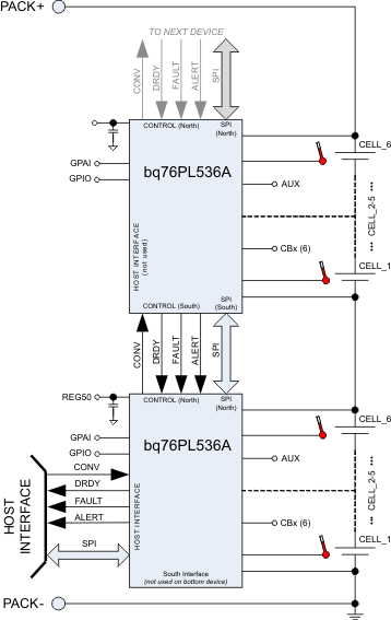
概略回路図
