SCDA034 May 2021 TMUX7208 , TMUX7209 , TMUX7212 , TMUX7234
1 Application Brief
Introduction
System design engineers keep striving for improved and often extremely high standards of system design. The challenge of designing an efficient and reliable electronic circuit often compels the engineers to choose multiple stage design involving integrated devices and discrete components to enhance signal chain performance. The consistent need to reduce the form factor and create an integrated solution forces engineers to look for innovative and cost-effective solutions.
This article looks at the key factors and challenges that affect system-level performance in process control environments. We will look at some challenges and how smart multiplexer device selection can help achieve those efficiency goals in some popular equipment in process control environment.
Measurement Accuracy With Multiplexers
Multiplexers help efficiently acquire data from multiple sensor inputs and optimize the I/O utilization in a single ADC application. Multiplexers help reduce the overall number of components and usually is a step just before the signal conditioning circuit. Some of the factors affect the signal-chain performance directly by way of affecting the accurate measurement and signal integrity through the multiplexer device. We look at these factors and their impact on signal accuracy.
Leakage Current (ILeakage)
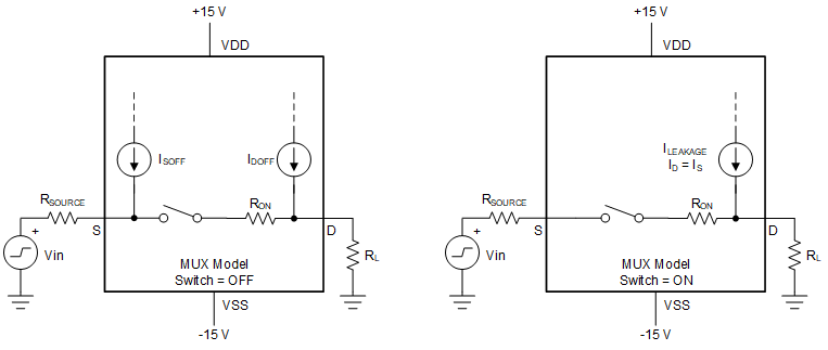
The multiplexer leakage current flows through the input impedance (RSOURCE) which results in the offset error that affects the measurement. Further temperature variations can amplify the offset DC error and introduce linearity errors.
Low leakage current specifications limit the DC error introduced at the output and optimize the measurement.
Figure 1-1 shows the simplified model of MUX leakage current flow when the switch is ON and when it is OFF.
 Figure 1-1 Simplified Model of MUX Leakage Current Flow
The voltage error introduced by the leakage current at the input side when the switch is ON is represented by Equation 1:
When the switch is off, leakage current flows through the terminal introducing the DC offset error at the output. On-state leakage current directly influences the introduction of the DC error at the output. While the leakage current cannot be entirely eliminated, we can try to minimize the same to limit the error.
On-Resistance (RDS(ON))
The drain-to-source on-resistance of a switch can introduce variations and gain error, which produce signal dependent distortion. RON, with the MUX output impedance or load resistance, create a voltage divider as shown in Figure 1-1. A smaller RON leads to smaller errors. Lower flatness makes correction of output code more accurate. Similarly, RON drifts over temperature limits accuracy and degrades the linearity of VOUT. RON flatness controls and limits the accuracy over the dynamic voltage range.
On-Capacitance (CON)
The on-capacitance affects settling behavior of multiplexers and hence transient performance of the system. Higher CON can introduce distortion in systems when input channels are switched at a very fast rate. The on-capacitance + load capacitance along with input resistance determines setting time for a multiplexed input system.
Charge Injection (QINJ)
QINJ is a measure of unwanted charge due to the redistribution voltage when a switch goes from on to the off state. The charge within the device gets redistributed and can be pushed to the output when the device turns on and off. During the fast switching action this phenomenon is much more pronounced and results in voltage error at the output.
Measuring the Flow of Moving Fluid (Gas or Liquid)
Flowmeters are sophisticated measuring devices that employ a range of technologies designed to quantify the rate or volume of a moving fluid, either liquid or gas. Accurately measuring flow rates in various process streams is critical to ensure proper equipment operation and to maximize plant efficiency.
Flowmeter Accuracy
Within the standard range of optimal flow, one can expect the flowmeter considered here to be accurate to ±0.5 percent of rate or reading. Depending on the technology employed, various flowmeter technologies have varying accuracy.
Ultrasonic flowmeters use time of flight (ToF) of an ultrasonic wave and its dependency and behavior in the medium using two transducer pairs for upstream and downstream paths. The flight time for the signal can be calculated using the known velocity of sound and length between the transducers. Ultrasonic transducers are placed across the cross-section of the pipe and ultrasonic pulses are transmitted and received by transducers on either side.
Other flowmeter techniques like magnetic flowmeter work on the basic principle of Faraday’s law. A conductive fluid such as water produces a magnetic field in the coils placed perpendicular to the flow of the fluid. Electrically charged particles of a fluid cross the artificial magnetic field generated by two field coils, an electric voltage is induced, which is a measure of the flow.
In either of the cases, capturing the input sensor signal and measuring accurately while eliminating the noise in the or DC error at the output is key to the accuracy of the system. In the case of smaller signal level at the input (nA or µV range), makes this task even more arduous with large DC error introduced.
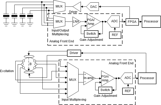
Figure 1-2 shows the input sensor signal being captured and fed to the Input Multiplexer before being sent to ADC for processing.
 Figure 1-2 Analog Front-End Implementation for Ultrasonic and Magnetic Flowmeter
Use a multiplexer to multiplex the input excitation signal to the multiplexer and optimize the number of signal-conditioning circuits employed. In a scenario where multiple sensor inputs are to be measured and processed, multiplexers with low leakage and low RON are preferred to limit the DC error to a minimum. Use the TMUX7208, and 8:1, 1-channel multiplexer or TMUX7209, 4:1, 2-channel multiplexers with 4-Ω RDS(ON) (typ) and 0.04-nA (typ) leakage current and 3-pC charge injection to multiplex the input excitation signals.
Multiplexers are also used to adjust the gain profile in the feedback loop in the closed-loop system. TS5A3159 ( 2:1 × 1 channel) with 0.75-Ω RDS(ON) or TMUX7212 (1:1 × 4 channel) with 1.7-Ω RDS(ON) and very low leakage current, 0.1 nA (typ) can be used for this purpose keeping the DC error at minimum.
Analog Input/Output Modules
A Programmable Logic controller (PLC) or distributed control system (DCS) module, is a ruggedized industrial computer control system that continuously monitors the state of input devices and makes decisions controlled by a custom program and fault diagnostics. The Analog Input Module (AIN) is a key subsystem in the PLC. PLC units are often designed to house different types of input modules to monitor different types of real world parameters (like voltage, current, temperature, pressure, and so forth), or receive analog or digital input signals from the sensors, or other sub systems before being fed to the ADC for further processing.
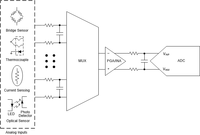
Analog input modules in control systems often switch sensors such as pH, optical, humidity, motion, or temperature sensors. All of these sensors exhibit high output impedance, which can vary in the range of few hundred kilo-ohms. Also, VOUT of the MUX is usually connected to the non-inverting terminal of an operational amplifier, which exhibits high input impedance. Source impedance (combined with the multiplexer RON and the input impedance of the operational amplifier) and the leakage of the multiplexer impact the accuracy of the measurement. Having RON (RON flatness) which is significantly lower than the input impedance of the operational amplifier greatly reduces the error caused by the multiplexer.
High common-mode signals at the input further amplify the DC error and affect the signal measurement accuracy or resolution and linearity with high or varying RDS(ON) of the switching component. This variation or DC error at the output seriously affects the data acquisition and affects the system accuracy.
Low RON, low leakage (nA range), low capacitance (low pF), switches are most commonly used in high-impedance systems when a higher precision and lower error conversion is desired.
 Figure 1-3 Multiplexed Analog Input Front End
Use the TMUX7208 (8:1, 1 channel) multiplexer with 4-Ω (typ) on-resistance and 5-nA (max) leakage current to multiplex the input sensor signals before being processed by the ADC. In the case of high common-mode voltage riding over the supply rails or the high-input voltage overshoot situations, use a fault-protected multiplexer like the TMUX7308F (8:1, 1 channel, fault protected) with 20-pF CON and low charge injection of 13 pC and ±60-V overvoltage protection, thereby providing system protection.
Select the TMUX7209 (4:1, 2 channel) to support the 4-channel differential voltage input for each ADC. For handling the isolated channel input system, use the TMUX7212 (1:1, 4 channel) with very low on-resistance and leakage multiplexer retaining the optimal system performance.
Conclusion
Modern day systems throw a new challenge to designers with the increased complexity. System efficiency is a measure of the signal measurement accuracy and the signal integrity. Any system is as good as its data acquisition and processing. DC error and the output variations are a result of combined effect of source resistance, input and output impedance, leakage current and on-capacitance. It is recommended that designers choose precision multiplexers with very low levels of leakage current, on-resistance, and charge injection.