SCDA040 January 2022 TMUX7308F , TMUX7412F , TMUX7462F
1 Application Brief
Modern-day system performance and safety requirements often result in additional protection circuits, which results in use of multiple discrete components. This involves additional cost, design time, and increased component count and PCB real estate. This article discusses new fault protected switch-based system design and associated benefits along with the performance advantage against traditional discrete design approaches.
The new state-of-the-art range of fault-protected multiplexers supported by silicon over oxide processes with precision performance ease the pain of the designers. Fault-protected multiplexers provide an additional layer of protection to the systems against all overshoot and overvoltage instances. TI’s new range of TMUX73xxF and TMUX74xx switches use the new process technology to bring this novel protection feature to make designs more integrated and safer.
Traditional Discrete Protection Switch vs Fault-Protected Switch
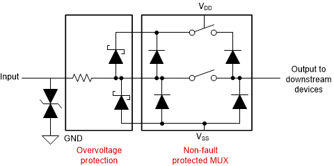
Figure 1-1 shows the traditional implementation of a discrete circuit using discrete components. The switch side has the ESD diodes for each of the supply rails. The ESD diodes are provided at both the input and output side of the switch to minimize the leakage current. Overvoltage protection is achieved by the external components like Schottky diodes of various ratings to clamp the overvoltage at the input. Series resistors are used to limit the current. Schottky diodes may be omitted, which increases the current-limiting resistor further introducing additional offset. Bidirectional TVS is used for additional protection.
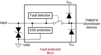
On the other side, the fault protected switch design (Figure 1-2), ESD diodes are replaced by the ESD cells which provide the desired voltage range depending on the limitation of the process. The ESD diodes at the output remain as there generally it is not a requirement for protection at the output side. The ESD cells on the input side provide excellent protection against ESD instances as well, which is as good as the discrete ESD diodes, if not better.

Figure 1-1 Discrete Protection

Figure 1-2 Integrated Fault Protection
The fault-protected multiplexer can be introduced in between the signal input and the signal conditioning circuit such as ADC, MCU, or FPGA. The multiplexer provides the protection to the downstream components against all instances of overvoltage and miswiring. The fault-protected multiplexers like TMUX7308F (8:1, 1-channel multiplexer) and TMUX7412F (1:1, 4-channel low RON, multiplexer) provide excellent protection in overvoltage and common-mode voltage.
- ±5-V to ±22-V dual supplies, 8-V to 44-V single supply
- ±60-V voltage protection under powered off conditions
- ±60-V voltage protection with regard to ground
- ±85-V voltage protection from source to supply or from source to drain
- Non-fault channels will operate normally
- Interrupt flags to indicate fault status
- Latch-up immunity
Fault Protection in Analog I/O Module
Analog input protection for high-performance signal chains is often a pain point for system designers. There is typically a significant trade-off between analog performance (such as leakage and on resistance) and the level of protection that can be offered by discrete components.
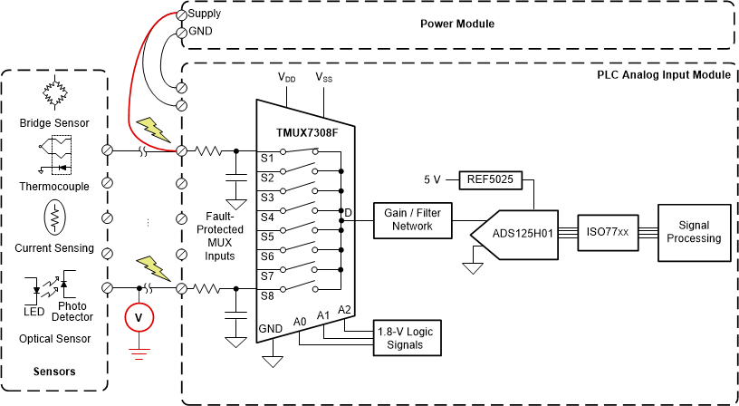
In analog input programmable logic controllers (PLC) a multiplexer is often used to switch multiple sensors to a single ADC. By using a multiplexer like the TMUX7308F or TMUX7309F, the number of components in the system can be reduced to save system cost and size and increase robustness. In a PLC module a ±10-V and ±15-V input signal range is common for interacting with external field transmitters and sensors; however, there are a number of fault cases that may occur that can damage many of the integrated circuits. Such fault conditions may include, but are not limited to, human error from miswiring connections, EOS (transient conditions above standard MUX ratings as well as powered off protection causing damage, system failure), latch up failures, and so forth.

Figure 1-3 Multiplexed Input Module
In the case of the RTD input module, a device like the TMUX7462F (1:1, 4-channel protector device) can be used to protect the analog input (AIN) channels to the ADC against the miswiring or overvoltage and overshoot situations. Working with thermocouple inputs requires additional overvoltage protection because thermocouples work at a higher supply voltage which may get passed to the downstream components and damage the circuit. This device also has the user-defined threshold fault protection (secondary voltage VFP and VFN) and fault detection functions providing additional control and monitoring.
Summary
Replacing traditional discrete protection components with overvoltage protected switches and multiplexers can simplify the design and provide many system benefits in a precision signal chain. Furthermore, integrated protection provides robustness to the system design and high density WQFN packages provide PCB space saving as well.
Reference
- Texas Instruments, A Basic Guide to RTD Measurements application note