SLLA569A March 2022 – July 2022 DRV8706-Q1
1 Application Brief
Imagine being stuck in traffic listening to music on the radio and a disturbance comes through and ruins your favorite part or interrupts the important news broadcast. Thankfully, cars are designed to meet the Comité International Spécial des Perturbations Radioélectriques (CISPR25) standards, so interruptions like these are avoided.
CISPR25 contains limits and procedures for the measurement of radio disturbances in the frequency range 150 kHz to 2.5 GHz. The frequency range defined in the standard covers both conducted and radiated emissions. For this article, the focus is solely on conducted emissions. CISPR25 defines two methods for conducted emissions testing: current probe method and voltage method. Both methods can be used to determine if the device under test (DUT) passes or fails the emission test limits. Customers generally require either the current probe method or voltage method. The preference for which method is chosen, comes down to the Original Equipment Manufacturer (OEM) requirements.
The motivation for this article came from a request to test a device in accordance to CISPR25. The customer provided conducted emissions results using the current probe method, and at Texas Instruments (TI), we tested using the voltage method. In addition, the customer-limit requirements were given in the units of dBm. This sparked curiosity into understanding the relationship between the measurement methods and the conversion between the units dBm, dBµA, and dBµV. The case in question was if the different methods and units are interchangeable.
CISPR25 Test Setup
In general, the test equipment needed is: Reference Ground Plane, Power Supply, Artificial Network, and a Load Simulator. Figure 1-1 and Figure 1-2 show the physical test set-up for the voltage method remote ground and current probe method remote ground respectively. The full test setup and requirements are outlined in the Comité International Spécial des Perturbations Radioélectriques (CISPR25).
The artificial network, also known as a Line Impedance Stabilizer Network (LISN), is placed directly on the reference ground plane. The purpose of the LISN is to stabilize the impedance detected by the DUT looking at the direct current (DC) battery and to block external noise that exists on the power cables. From Figure 1-1 and Figure 1-2, it is evident that there are two separate LISNs, LISN1 and LISN2, connected to the negative and positive terminals of the battery respectively. When using the voltage method remote ground test setup, it is important that LISN2, which is not connected to the measuring instrument, is terminated with a 50-Ω load. This impedance match is to ensure that there are no reflections back into the source and the measurements are valid.
CISPR25 conducted emissions measurements for voltage method are performed in the frequency range 0.15 MHz to 108 MHz and, for current probe method, 0.15 MHz to 245 MHz. The test set-up and measurement points for the two methods are also different. Referring to Figure 1-1, the voltage method takes the measurement directly from the artificial network by connecting one end of the cable to LISN1 and the other end to the spectrum analyzer. However, for the current probe method, shown in Figure 1-2, the probe is clamped around the entire wire harness to the DUT and is then connected to the spectrum analyzer to take the measurement.
Simulations and Results
Simulations were performed using PSPICE-FOR-TI. See Figure 1-3 for the schematic. A 12-V DC source is used to model the car battery. The positive LISN model includes L1, C1, C2, R1, and R2 connected to the positive terminal of the battery. Similarly, the negative LISN is connected to the negative terminal of the battery. As previously mentioned, the 50-Ω resistors, R2 and R7, are there to represent the 50-Ω termination into the spectrum analyzer and a dummy load. Lastly, an ideal sinusoidal current source was used to model the DUT. To simulate the voltage method test, we measured the voltage across the 50-Ω resistor. Since PSPICE-for-TI requires a node to measure current, a 1-mΩ resistor was placed in series with the ideal source for the current probe method simulation.
Theory says that the current will always take the path of least impedance. Therefore, in simulation, it is expected that most of the current would flow back through the 50-Ω resistor rather than the inductor. However, at the lower frequencies, the impedance of the 5-µH inductor is lower compared to that of the 50-Ω resistor due to the series 100-nF capacitor. It is not until about the 1.5-MHz range where the impedance of the inductor starts to surpass the resistor.
To compare the simulation results, the frequency of the ideal sinusoidal current source was changed in incremental steps from 100 kHz to 108 MHz. The frequency spectrum of the waveform was obtained using the Fast Fourier Transform (FFT) function in PSPICE-FOR-TI. The FFT data gave the peak measurements in mV for voltage method and µA for current probe method at the specified frequency.
To have a fair comparison of the two methods, the data was converted to dBµA, dBµV, and dBm using the following equations.
When converting units of dBµA and dBµV to dBm, the values are expected to be the same since virtually the same test was run. The goal is to only take one test and convert the results to dBµV, dBµA, or dBm and see the relation to pass or fail for both the voltage method and the current probe method. Table 1-1 and Table 1-2 show the simulated results at 0.15 MHz and 100 MHz. From these results, it is clear to see that at the higher frequencies, the current probe method and voltage method measurements are much more comparable than at the lower frequencies.
| Voltage Method | Current Probe Method |
|---|---|
| 1.2 mV | 249.9 μA |
| 27.4 dBµA | 47.9 dBµA |
| 61.4 dBµV | 81.9 dBµV |
| –45.6 dBm | –25.1 dBm |
| Voltage Method | Current Probe Method |
|---|---|
| 11.3 mV | 237.4 μA |
| 47.1 dBµA | 47.5 dBµA |
| 81.1 dBµV | 81.5 dBµV |
| –25.9 dBm | –25.50 dBm |
Table 1-3 shows the CISPR25 passing limits at the given frequencies for voltage method and current probe method. The limits given for voltage method are from the CISPR25 standard, whereas the limits for current probe method are converted from the CISPR25 standard units, dBµA, to dBµV for comparison.
| Frequency (MHz) | Voltage Method (dBµV) | Current Probe Method (Converted to dBµV) |
|---|---|---|
| 0.15 to 30 | 70 | 84 |
| 0.53 to 1.8 | 54 | 60 |
| 5.9 to 6.2 | 53 | 53 |
| 76 to 108 | 38 | 38 |
| 26 to 28 | 44 | 44 |
| 30 to 54 | 44 | 44 |
| 68 to 87 | 38 | 38 |
Table 1-3 shows that the standard accounts for the impact of LISN impedance characteristics across the frequency spectrum. For example, the difference for peak measurements at 0.15 MHz to 0.3 MHz from current probe method to voltage method is 84 dBµV – 70 dBµV = 14 dBµV, whereas the simulated data at 0.15 MHz in Table 1-1 shows a difference of 81.93 dBµV – 61.36 dBµV = 20 dBµV. In the higher frequency bands, the standard and the converted values are the same. For example, the difference for peak measurements at 76 MHz to 108 MHz is 38 dBµV – 38 dBµV = 0 dBµV, and our simulated data at 100 MHz in Table 1-2 shows a difference of 25.93 dBµV – 25.50 dBµV ≅ 0.4 dBµV.
CISPR25 Lab Results
To verify the simulation results, CISPR25 conducted emissions measurements were taken for both methods. An automotive power window lift reference design board featuring DRV8706-Q1 was used for the conducted emissions testing. For the current probe method, the probe was placed around the input power wire only. Since voltage method is measured at the LISN connected to the input power, the best comparison is to measure current around the input power wire only to ensure we are measuring both differential mode and common mode noise.
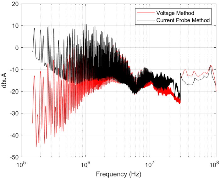
To compare these two lab results, the voltage method results were converted to dBµA using Equation 3. The converted voltage method results were then plotted against the current probe method results in dBµA.
 Figure 1-4 Current Probe Method vs
Voltage Method
Figure 1-4 Current Probe Method vs
Voltage MethodThe current probe method results tend to be higher than the voltage method below 5 MHz. This is expected due to the impedance characteristics of the LISN network. Below 5 MHz, some current will flow through the 5-μH inductor in the LISN instead of the voltage method measurement location at the 50-Ω load.
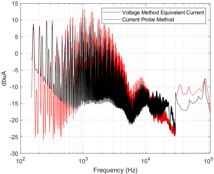
To better compare these results, calculate the current through the input wire from the measurement obtained in voltage method and compare this with the measurement obtained in current probe method. This input wire current is calculated using known impedance values of the LISN.
Now, plot the current probe method results against the converted voltage method results in dBµA.
 Figure 1-5 Current Probe Method vs
Voltage Method Equivalent Current
Figure 1-5 Current Probe Method vs
Voltage Method Equivalent CurrentFrom this data, we can conclude that the current probe method and the voltage method yield very similar results. Below 5 MHz, the results are near identical. While above 5 MHz, there is a small difference between the two methods.
There are a few possible explanations to account for this difference in results at the higher frequencies. The first is current probe location. CISPR 25 defines two specific current probe locations 50 mm and 750 mm from the DUT. By placing the current probe at different distance from the DUT, certain harmonics become more apparent at specific probe locations. A second possible explanation is the current probe diameter or aperture. In general, the smaller the aperture, the more efficient the coupling. Current probes with a larger aperture are optimized either for low- or high-frequency coupling efficiency. Both current probe location and aperture are possible explanations for the larger variation in results for current probe and voltage method at higher frequencies.
In summary, it is important to note that CISPR25 conducted emission levels for current probe and voltage method were selected to give near equal limit lines. In simulation we learned that at low frequencies the impedance of the 5-μH inductor in the LISN network allows for some current to flow through it rather than flow through the 50-Ω resistor. This results in voltage method having lower limits below 5 MHz. Overall, both methods are widely used and it is important to understand how the two methods compare.