SNAA380 March 2023 LMX2820
Introduction
Existing radio frequency (RF) sampling transceivers like the AFE7950 operate up to X-band (12 GHz) frequencies. Operating into the entire K-band (12–40 GHz) requires a modified approach. One design uses a direct conversion modulator and demodulator to mix the baseband signal directly to and from the K-band frequency. An alternative option uses an RF sampling transceiver as a high-frequency intermediate frequency (IF) stage within a superheterodyne architecture where the IF frequencies are mixed up or down into the desired K-band. Both designs require a high frequency, low-phase-noise synthesizer to serve as the LO source for the mixer.
Figure 1 shows a typical superheterodyne transceiver architecture using RF sampling data converters suitable for operation in K-band. The data converter outputs or inputs operate up through X-band. The mixing stage converts to or from K-band. Equation 1 determines the LO frequency based on required RF band and desired IF frequency.
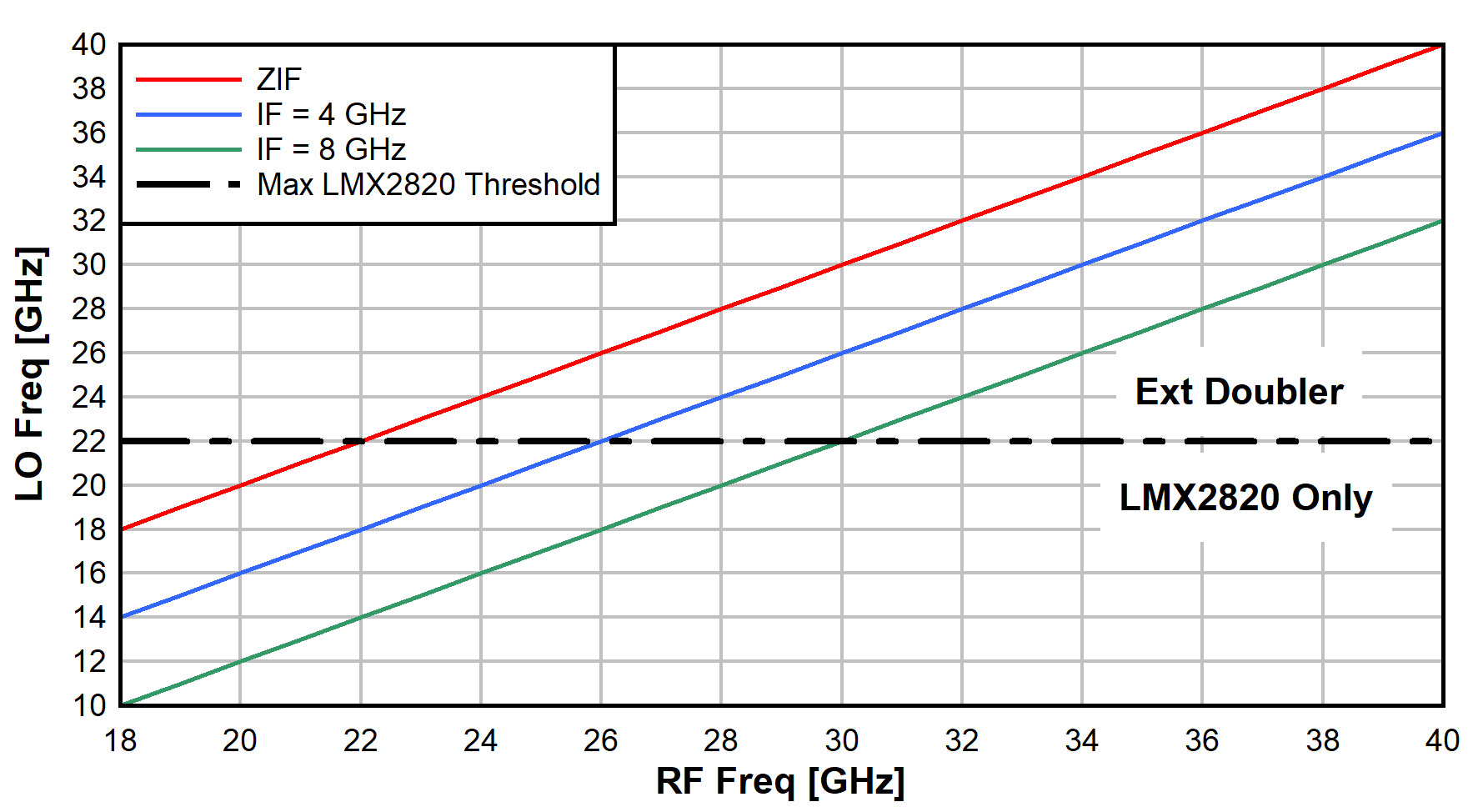
The LMX2820 RF synthesizer natively supports operation up to 22 GHz. This range supports the Ku-band (12–18 GHz) directly. For support in the K-band (18-27 GHz) and the Ka-band (26.5 – 40 GHz), a higher frequency is sometimes needed depending on the IF frequency selection. Figure 2 shows a plot of the LO frequency as a function of RF band for three different IF frequencies: 0 Hz (ZIF), 4 GHz, and 8 GHz. For combinations of IF frequency and RF band frequencies that require an LO exceeding the 22-GHz threshold of the LMX2820, cascading an external doubler adequately extends the output frequency.
 Figure 1 K-Band
Superheterodyne Transceiver
 Figure 2 LMX2820
Threshold for External Doubler
Figure 2 LMX2820
Threshold for External DoublerFrequency Plan
The internal Voltage Controlled Oscillators (VCOs) in the LMX2820 support a range of 5.65–11.3 GHz. Internal dividers derive lower frequencies. An integrated doubler generates higher frequencies up to 22.6 GHz. An external doubler extends the frequency past 40 GHz.
This analysis uses the MACOM® XX1000-QT active doubler. The device operates up to 45 GHz and includes an output amplifier to increase the signal above 10 dBm which is sufficient as a mixer LO.
The target frequency is 26.4 GHz. This is desirable for many mainstream Ka-band applications. For this frequency choice, the fundamental VCO frequency in the LM2820 is 6.6 GHz. With the internal doubler engaged, the output frequency is 13.2 GHz. That frequency goes through the external doubler to get to 26.4 GHz.
As with any multiplier or doubler, the fundamental frequency is not completely suppressed. Since this approach is essentially a multiply-by-4 operation, it is expected to observe remnants of the fundamental and the second harmonic. For best operation, provide some filtering around the output signal to eliminate the subharmonics before the subharmonics infect the mixers.
Phase Noise Performance
Figure 3 shows the design setup block diagram. The reference frequency to the LMX2820 is 100 MHz generated from a Rohde SMA100B signal generator. The internal reference doubler creates a PFD frequency of 200 MHz. The internal LMX2820 VCO is tuned to 6.6 GHz with an N-divider setting of 33.
 Figure 3 Measurement
Block Diagram
Figure 3 Measurement
Block DiagramOnce the LMX2820 phase-locked loop (PLL) is properly locked, the device either outputs the frequency directly, divides the frequency down, or multiplies the frequency up by 2. With the multiplier engaged, the output frequency is 13.2 GHz. That frequency injects into the external doubler to generate 26.4 GHz.
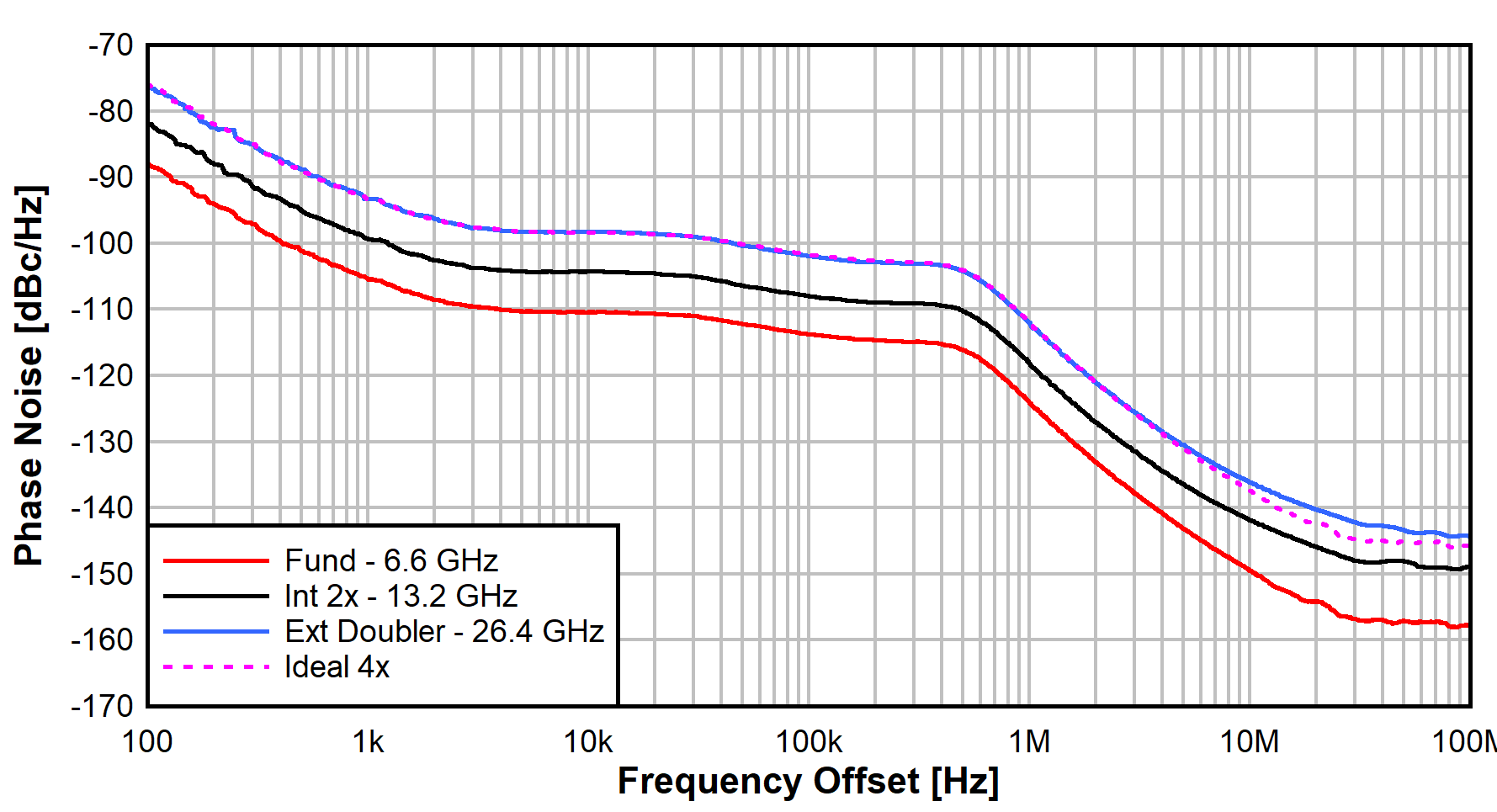
Figure 4 shows the phase noise performance of three frequencies: the fundamental tone at 6.6 GHz, the internally doubled tone at 13.2 GHz, and the externally doubled tone at 26.4 GHz. The output power is just over 11 dBm at 26.4 GHz which is in the proper realm for a mixer LO level. The plot also depicts the fundamental frequency ideally multiplied up (20 × log(N)) by 4. The actual measurement matches the ideal case with only a slight increase in the noise floor at high-frequency offsets.
 Figure 4 Phase Noise
Plot
Figure 4 Phase Noise
PlotSubharmonic Performance
Subharmonics distort the mixing operation and create undesired spurs on the output. Table 1 shows the subharmonic spur performance for the setup.
| Tone | Freq | Power |
|---|---|---|
| Desired Tone | 26.4 GHz | 11.3 dBm |
| 1/2 HD | 13.2 GHz | –17 dBc |
| 1/4 HD | 6.6 GHz | –58 dBc |
The half-harmonic is only –17 dBc. Given the high output power of the desired tone, the half-harmonic absolute power is roughly –6 dBm. This level can sometimes be high enough to cause issues and require some filtering to eliminate the threat. The quarter-harmonic is less than –40 dBm; it is expected that this tone is low enough not to introduce any unwanted issues.
Subharmonic Filtering
For cases where the half-harmonic spur level is too high, introduce a high-pass (or band-pass) filter on the output to suppress the signal; however, creating a filter at 26 GHz is not a trivial activity. Fortunately, the selectivity requirements are low and the spacing is high which eases filter design. A lumped element filter is impractical at these frequencies as the component values become unrealistically small and the parasitic contributions dominate. Alternatively, use a distributed open circuit stub line filter to notch the frequency at 13.2 GHz and pass 26.4 GHz.
The most basic filter is a single open-circuit stub that is a quarter-wave long at the subharmonic frequency. A quarter-wave stub presents an RF short at the subharmonic frequency at the primary transmission line and suppresses that frequency. At the desired frequency, the stub looks like an open circuit at the transmission line and does not attenuate the signal.
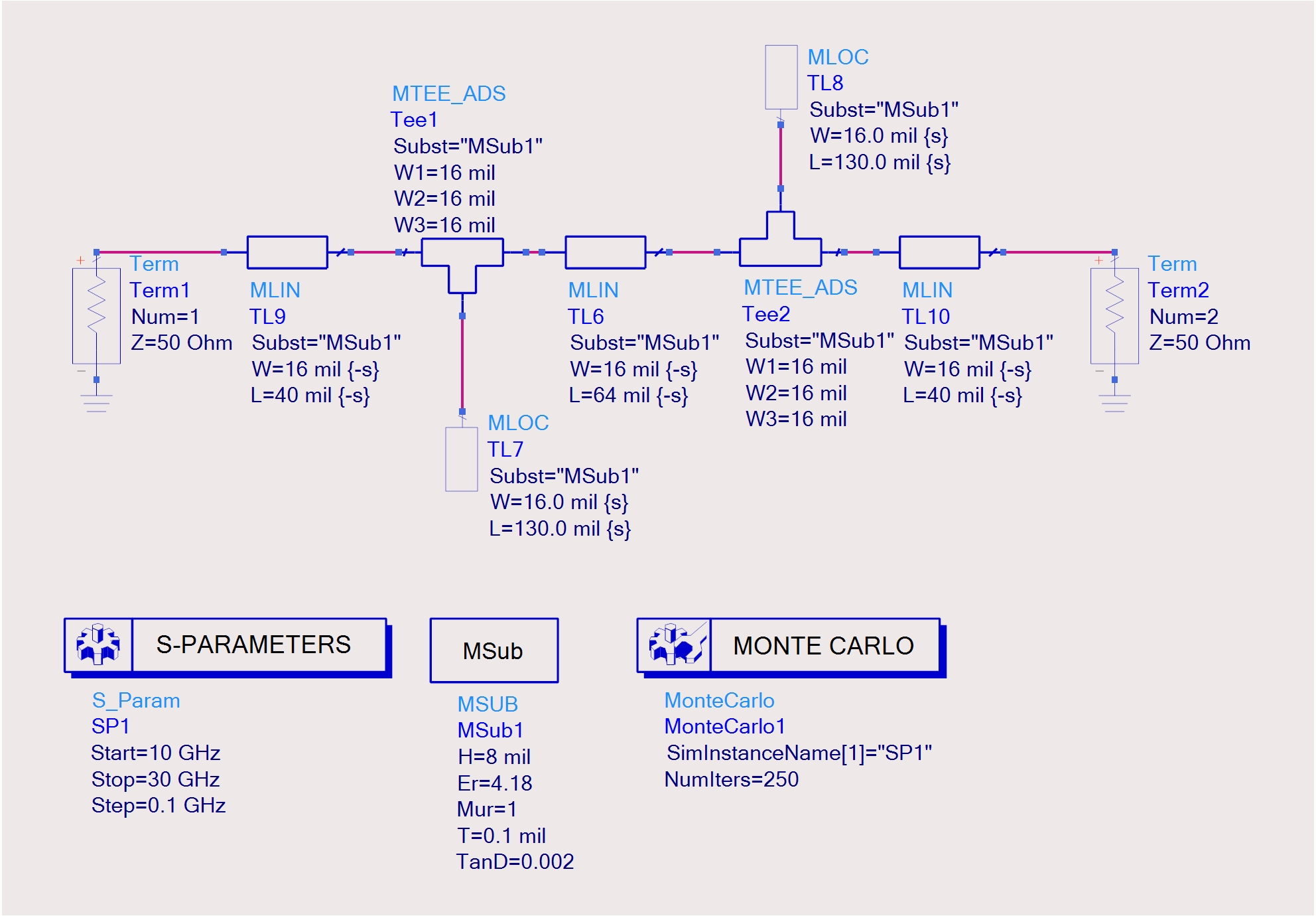
Though a single stub ideally provides over 40 dB of selectivity, the effective bandwidth is narrow. Given that the desired frequency and the subharmonic are just a single tone, a wide bandwidth notch is not required; however, it is a good idea to account for printed circuit board (PCB) manufacturing tolerances and three-dimensional radiation effects that sometimes unknowingly shift the exact center frequency. Using two quarter-wave stubs separated by an eighth-wave transmission line effectively creates two poles slightly separated in frequency to give an effective 20-dB down bandwidth of over 1 GHz. This notch allows for tolerance variations to occur while still achieving 20 dB or better selectivity. Figure 5 shows the Keysight ADS simulation schematic with the two stubs realized in micro-strip.
 Figure 5 Double-Stub
Subharmonic 13-GHz Notch Filter
Figure 5 Double-Stub
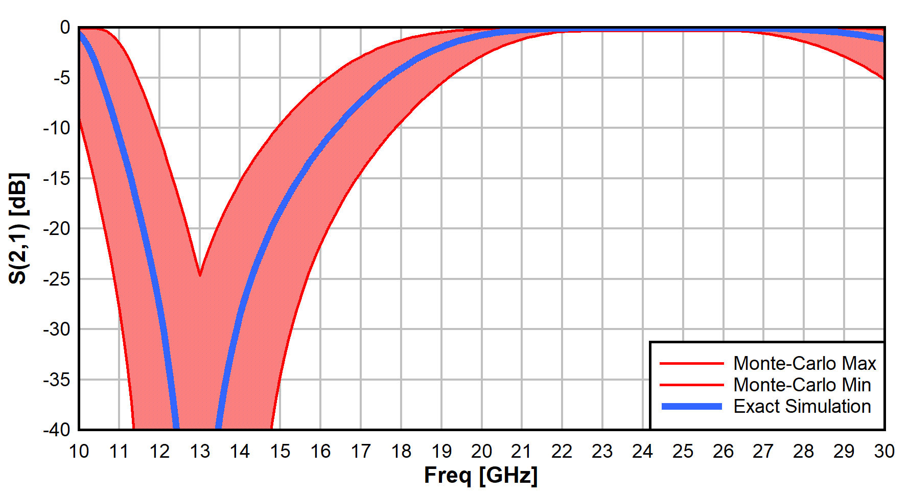
Subharmonic 13-GHz Notch FilterFigure 6 shows the exact simulated filter response. Also shown is the minimum and maximum extends of a 250-trial Monte-Carlo simulation where the trace widths and stub length are allowed to vary ±10%. The Monte-Carlo simulation achieves a minimum of 20 dB of selectivity with the inclusion of the tolerances. This filter is easy to realize on a PCB design, requires no additional parts, and consumes under 20 square mm of board area.
 Figure 6 13-GHz
Subharmonic Notch Filter Response
Figure 6 13-GHz
Subharmonic Notch Filter ResponseSummary
The LMX2820 plus external doubler is suitable for applications that require an LO source above 22 GHz. This design is good for communication systems, radar, and electronic warfare (EW) designs, and for satellite ground communication applications operating in the K- and Ka-band. Phase noise performance is good and tracks expected performance of a multiply-by-4 system from the fundamental VCO performance of the LMX2820. The design is compact and programmable to meet a variety of frequency generation needs.
References
- Texas Instruments, LMX2820 22.6-GHz Wideband PLLatinum™ RF Synthesizer With Phase Synchronization and JESD204B Support data sheet
- Texas Instruments, AFE7950 Super-Heterodyne Solution for K-Band application note
- Texas Instruments, LMX2820 RF Synthesizer Phase Noise Improvement With Alternative Topologies application note