TIDT224 March 2021
1 Description
This isolated primary-side regulated (PSR) flyback converter provides dual 15-V outputs at 100 mA each. It was designed to provide bias power for a rotor coil excitation gate-driver in motor and inverter applications. The isolated output voltage is sampled from the primary-side flyback voltage, eliminating the need for an optocoupler, voltage reference, or third winding from the transformer for output voltage regulation. It offers a high level of integration, low cost, and high efficiency in a compact form factor.
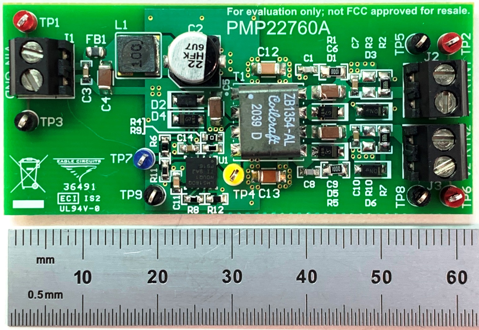
 Figure 1-1 Top-Side Photo of PCB