JAJSCC3B June   2016  – July 2018 CC1350

PRODUCTION DATA.  

  1. 1デバイスの概要
    1. 1.1 特長
    2. 1.2 アプリケーション
    3. 1.3 概要
    4. 1.4 機能ブロック図
  2. 2改訂履歴
  3. 3Device Comparison
    1. 3.1 Related Products
  4. 4Terminal Configuration and Functions
    1. 4.1 Pin Diagram – RSM Package
    2. 4.2 Signal Descriptions – RSM Package
    3. 4.3 Pin Diagram – RHB Package
    4. 4.4 Signal Descriptions – RHB Package
    5. 4.5 Pin Diagram – RGZ Package
    6. 4.6 Signal Descriptions – RGZ Package
  5. 5Specifications
    1. 5.1  Absolute Maximum Ratings
    2. 5.2  ESD Ratings
    3. 5.3  Recommended Operating Conditions
    4. 5.4  Power Consumption Summary
    5. 5.5  RF Characteristics
    6. 5.6  Receive (RX) Parameters, 861 MHz to 1054 MHz
    7. 5.7  Receive (RX) Parameters, 431 MHz to 527 MHz
    8. 5.8  Transmit (TX) Parameters, 861 MHz to 1054 MHz
    9. 5.9  Transmit (TX) Parameters, 431 MHz to 527 MHz
    10. 5.10 1-Mbps GFSK (Bluetooth low energy) – RX
    11. 5.11 1-Mbps GFSK (Bluetooth low energy) – TX
    12. 5.12 PLL Parameters
    13. 5.13 ADC Characteristics
    14. 5.14 Temperature Sensor
    15. 5.15 Battery Monitor
    16. 5.16 Continuous Time Comparator
    17. 5.17 Low-Power Clocked Comparator
    18. 5.18 Programmable Current Source
    19. 5.19 DC Characteristics
    20. 5.20 Thermal Characteristics
    21. 5.21 Timing and Switching Characteristics
      1. 5.21.1 Reset Timing
        1. Table 5-1 Reset Timing
      2. 5.21.2 Wakeup Timing
        1. Table 5-2 Wakeup Timing
      3. 5.21.3 Clock Specifications
        1. Table 5-3 24-MHz Crystal Oscillator (XOSC_HF)
        2. Table 5-4 32.768-kHz Crystal Oscillator (XOSC_LF)
        3. Table 5-5 48-MHz RC Oscillator (RCOSC_HF)
        4. Table 5-6 32-kHz RC Oscillator (RCOSC_LF)
      4. 5.21.4 Flash Memory Characteristics
        1. Table 5-7 Flash Memory Characteristics
      5. 5.21.5 Synchronous Serial Interface (SSI) Characteristics
        1. Table 5-8 Synchronous Serial Interface (SSI) Characteristics
    22. 5.22 Typical Characteristics
    23. 5.23 Typical Characteristics – Sub-1 GHz
    24. 5.24 Typical Characteristics – 2.4 GHz
  6. 6Detailed Description
    1. 6.1  Overview
    2. 6.2  Main CPU
    3. 6.3  RF Core
    4. 6.4  Sensor Controller
    5. 6.5  Memory
    6. 6.6  Debug
    7. 6.7  Power Management
    8. 6.8  Clock Systems
    9. 6.9  General Peripherals and Modules
    10. 6.10 Voltage Supply Domains
    11. 6.11 System Architecture
  7. 7Application, Implementation, and Layout
    1. 7.1 Application Information
    2. 7.2 TI Design or Reference Design
  8. 8デバイスおよびドキュメントのサポート
    1. 8.1  デバイスの項目表記
    2. 8.2  ツールとソフトウェア
    3. 8.3  ドキュメントのサポート
    4. 8.4  テキサス・インスツルメンツのローパワーRF Webサイト
    5. 8.5  追加情報
    6. 8.6  コミュニティ・リソース
    7. 8.7  商標
    8. 8.8  静電気放電に関する注意事項
    9. 8.9  Export Control Notice
    10. 8.10 Glossary
  9. 9メカニカル、パッケージ、および注文情報
    1. 9.1 パッケージ情報

パッケージ・オプション

デバイスごとのパッケージ図は、PDF版データシートをご参照ください。

メカニカル・データ(パッケージ|ピン)
  • RSM|32
  • RGZ|48
  • RHB|32
サーマルパッド・メカニカル・データ
発注情報

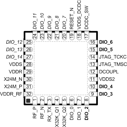
Pin Diagram – RHB Package

Figure 4-2 shows the RHB pinout diagram.

CC1350 RHB_pinout_CC13xx.gifFigure 4-2 RHB (5-mm × 5-mm) Pinout, 0.5-mm Pitch
Top View

I/O pins marked in Figure 4-2 in bold have high-drive capabilities; they are as follows:

  • Pin 8, DIO_2
  • Pin 9, DIO_3
  • Pin 10, DIO_4
  • Pin 15, DIO_5
  • Pin 16, DIO_6

I/O pins marked in Figure 4-2 in italics have analog capabilities; they are as follows:

  • Pin 20, DIO_7
  • Pin 21, DIO_8
  • Pin 22, DIO_9
  • Pin 23, DIO_10
  • Pin 24, DIO_11
  • Pin 25, DIO_12
  • Pin 26, DIO_13
  • Pin 27, DIO_14