JAJSDU9A February 2017 – May 2017 DLPA1000
PRODUCTION DATA.
- 1 特長
- 2 アプリケーション
- 3 概要
- 4 改訂履歴
- 5 Pin Configuration and Functions
- 6 Specifications
-
7 Detailed Description
- 7.1 Overview
- 7.2 Functional Block Diagram
- 7.3 Feature Description
- 7.4 Device Functional Modes
- 7.5 Programming
- 7.6
Register Maps
- 7.6.1 Chip ID (CHIPID) Register (address = 0x00h) [reset = A6h]
- 7.6.2 Enable (ENABLE) Register (address = 0x01h) [reset = 3h]
- 7.6.3 Switch Transient Current Limit (IREG) Register (address = 0x02h) [reset = 28h]
- 7.6.4 SW4 LED DC Regulation Current, MSB (SW4MSB) Register (address = 0x03h) [reset = 0h]
- 7.6.5 SW4 LED DC Regulation Current, LSB (SW4LSB) Register (address = 0x04h) [reset = 0h]
- 7.6.6 SW5 LED DC Regulation Current, MSB (SW5MSB) Register (address = 0x05h) [reset = 0h]
- 7.6.7 SW5 LED DC Regulation Current, LSB (SW5LSB) Register (address = 0x06h) [reset = 0h]
- 7.6.8 SW6 LED DC Regulation Current, MSB (SW6MSB) Register (address = 0x07h) [reset = 0h]
- 7.6.9 SW6 LED DC Regulation Current, LSB (SW6LSB) Register (address = 0x08h) [reset = 0h]
- 7.6.10 Analog Front End Control (AFE) Register (address = 0x0Ah) [reset = 0h]
- 7.6.11 Strobe Decode - Break Before Make Timing Control (BBM) Register (address = 0x0Bh) [reset = 0h]
- 7.6.12 Interrupt (INT) Register (address = 0x0Ch) [reset = X]
- 7.6.13 Interrupt Mask (MASK) Register (address = 0x0Dh) [reset = 0h]
- 7.6.14 Password (PASSWORD) Register (address = 0x10h) [reset = 0h]
- 7.6.15 System Configuration (SYSTEM) Register (address = 0x11h) [reset = 0h]
- 7.6.16 EEPROM User Register, Byte0 (BYTE0) (address = 0x20h) [reset = 0h]
- 7.6.17 EEPROM User Register, Byte1 (BYTE1) (address = 0x21h) [reset = 0h]
- 7.6.18 EEPROM User Register, Byte2 (BYTE2) (address = 0x22h) [reset = 0h]
- 7.6.19 EEPROM User Register, Byte3 (BYTE3) (address = 0x23h) [reset = 0h]
- 7.6.20 EEPROM User Register, Byte4 (BYTE4) (address = 0x24h) [reset = 0h]
- 7.6.21 EEPROM User Register, Byte5 (BYTE5) (address = 0x25h) [reset = 0h]
- 7.6.22 EEPROM User Register, Byte6 (BYTE6) (address = 0x26h) [reset = 0h]
- 7.6.23 EEPROM User Register, Byte7 (BYTE7) (address = 0x27h) [reset = 0h]
- 8 Application and Implementation
- 9 Power Supply Recommendations
- 10Layout
- 11デバイスおよびドキュメントのサポート
- 12メカニカル、パッケージ、および注文情報
パッケージ・オプション
デバイスごとのパッケージ図は、PDF版データシートをご参照ください。
メカニカル・データ(パッケージ|ピン)
- YFF|49
サーマルパッド・メカニカル・データ
発注情報
1 特長
- 降圧-昇圧DC/DCコンバータ付き、MOSFET内蔵の、高効率のRGB LEDドライバ
- 6つの低インピーダンス(100mΩ未満) MOSFETスイッチによるチャネル選択
- チャネルごとに独立の10ビット電流制御
- DMDレギュレータ
- インダクタ1つだけで動作
- VOFS: 8.5V
- VBIAS: 16V
- VRST: -10V
- リセット生成および電源シーケンシング
- RGB LEDストローブ・デコーダによりサポート
- 共通アノードRGB
- カソード-カソード-アノードRGB
- 33MHzのシリアル・ペリフェラル・インターフェイス(SPI)
- マルチプレクサによるアナログ信号の測定
- バッテリ電圧
- LED電圧、LED電流
- 光センサ(ホワイト・ポイント修正用)
- 外部温度センサ
- 監視および保護回路
- ダイの過熱警告およびサーマル・シャットダウン
- 低バッテリおよび低電圧誤動作防止
- 過電流および低電圧保護
- 49ボール、0.4mmピッチのDSBGAパッケージ
2 アプリケーション
3 概要
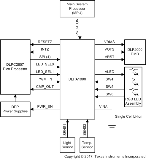
DLPA1000は、DLPC2607DLPデジタル・コントローラとともに使用するDLP2000デジタル・マイクロミラー・デバイス(DMD)専用のPMIC/RGB LEDドライバです。これらのチップセットを高い信頼性で使用するには、DLPA1000の使用が必須です。
製品情報(1)
| 型番 | パッケージ | 本体サイズ(公称) |
|---|---|---|
| DLPA1000 | DSBGA (49) | 2.40mm×2.40mm |
- 提供されているすべてのパッケージについては、巻末の注文情報を参照してください。
概略回路図
