JAJSDU1 August   2017 DRV5012

PRODUCTION DATA.  

  1. 特長
  2. アプリケーション
  3. 概要
  4. 改訂履歴
  5. Pin Configuration and Functions
  6. Specifications
    1. 6.1 Absolute Maximum Ratings
    2. 6.2 ESD Ratings
    3. 6.3 Recommended Operating Conditions
    4. 6.4 Thermal Information
    5. 6.5 Electrical Characteristics
    6. 6.6 Magnetic Characteristics
    7. 6.7 Typical Characteristics
  7. Detailed Description
    1. 7.1 Overview
    2. 7.2 Functional Block Diagram
    3. 7.3 Feature Description
      1. 7.3.1 Magnetic Flux Direction
      2. 7.3.2 Magnetic Response
      3. 7.3.3 Output Driver
      4. 7.3.4 Sampling Rate
      5. 7.3.5 SEL Pin
      6. 7.3.6 Hall Element Location
    4. 7.4 Device Functional Modes
  8. Application and Implementation
    1. 8.1 Application Information
    2. 8.2 Typical Applications
      1. 8.2.1 BLDC Motor Sensors Application
        1. 8.2.1.1 Design Requirements
        2. 8.2.1.2 Detailed Design Procedure
        3. 8.2.1.3 Application Curve
      2. 8.2.2 Incremental Rotary Encoding Application
        1. 8.2.2.1 Design Requirements
        2. 8.2.2.2 Detailed Design Procedure
        3. 8.2.2.3 Application Curve
    3. 8.3 Do's and Don'ts
  9. Power Supply Recommendations
  10. 10Layout
    1. 10.1 Layout Guidelines
    2. 10.2 Layout Example
  11. 11デバイスおよびドキュメントのサポート
    1. 11.1 デバイス・サポート
      1. 11.1.1 開発サポート
    2. 11.2 ドキュメントの更新通知を受け取る方法
    3. 11.3 コミュニティ・リソース
    4. 11.4 商標
    5. 11.5 静電気放電に関する注意事項
    6. 11.6 Glossary
  12. 12メカニカル、パッケージ、および注文情報

パッケージ・オプション

デバイスごとのパッケージ図は、PDF版データシートをご参照ください。

メカニカル・データ(パッケージ|ピン)
  • DMR|4
サーマルパッド・メカニカル・データ
発注情報

Pin Configuration and Functions

DMR Package
4-Pin X2SON With Exposed Thermal Pad
Top View
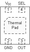
DRV5012 pkg.gif

Pin Functions

PIN I/O DESCRIPTION
NAME NO.
GND 2 Ground reference
OUT 3 O Push-pull CMOS output. Drives a VCC or ground level.
SEL 4 I CMOS input that selects the sampling rate: a low voltage sets 20 Hz; a high voltage sets 2.5 kHz.
VCC 1 1.65-V to 5.5-V power supply. TI recommends connecting this pin to a ceramic capacitor to ground with a value of at least 0.1 µF.
Thermal Pad PAD No-connect. This pin should be left floating or tied to ground. It should be soldered to the board for mechanical support.