SLCS144E July 2004 – October 2014 LM317L
PRODUCTION DATA.
- 1 Features
- 2 Applications
- 3 Description
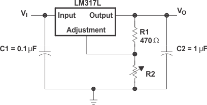
- 4 Simplified Schematic
- 5 Revision History
- 6 Pin Configuration and Functions
- 7 Specifications
- 8 Detailed Description
-
9 Application and Implementation
- 9.1 Application Information
- 9.2 Typical Application
- 9.3
General Configurations
- 9.3.1 Regulator Circuit With Improved Ripple Rejection
- 9.3.2 0-V to 30-V Regulator Circuit
- 9.3.3 Precision Current-Limiter Circuit
- 9.3.4 Tracking Preregulator Circuit
- 9.3.5 Slow-Turn On 15-V Regulator Circuit
- 9.3.6 50-mA Constant-Current Battery-Charger Circuit
- 9.3.7 Current-Limited 6-V Charger
- 9.3.8 High-Current Adjustable Regulator
- 10Power Supply Recommendations
- 11Layout
- 12Device and Documentation Support
- 13Mechanical, Packaging, and Orderable Information
パッケージ・オプション
デバイスごとのパッケージ図は、PDF版データシートをご参照ください。
メカニカル・データ(パッケージ|ピン)
- D|8
- PW|8
- PK|3
- LP|3
サーマルパッド・メカニカル・データ
- PK|3
発注情報
1 Features
- Output Voltage Range Adjustable 1.25 V to 32 V When Used With External Resistor Divider
- Output Current Capability of 100 mA
- Input Regulation Typically 0.01% Per Input-Voltage Change
- Output Regulation Typically 0.5%
- Ripple Rejection Typically 80 dB
- For Higher Output Current Requirements, See LM317M (500 mA) and LM317 (1.5 A)
2 Applications
- Electronic Points of Sale
- Medical, Health, and Fitness Applications
- Printers
- Appliances and White Goods
- TV Set-Top Boxes
3 Description
The LM317L device is an adjustable, 3-terminal, positive-voltage regulator capable of supplying 100 mA over an output-voltage range of 1.25 V to 32 V. It is exceptionally easy to use and requires only two external resistors to set the output voltage.
Device Information
| PART NUMBER | PACKAGE | BODY SIZE (NOM) |
|---|---|---|
| LM317L | SOIC (8) | 4.90 mm × 3.91 mm |
| TO-92 (3) | 4.30 mm × 4.30 mm | |
| SOT-89 (3) | 4.50 mm × 2.50 mm | |
| TSSOP (8) | 3.00 mm × 4.40 mm |
4 Simplified Schematic