SNVSA42B June 2015 – May 2016 LM53602-Q1 , LM53603-Q1
PRODUCTION DATA.
- 1 Features
- 2 Applications
- 3 Description
- 4 Revision History
- 5 Device Comparison Table
- 6 Pin Configuration and Functions
- 7 Specifications
- 8 Detailed Description
- 9 Application and Implementation
- 10Power Supply Recommendations
- 11Layout
- 12Device and Documentation Support
- 13Mechanical, Packaging, and Orderable Information
パッケージ・オプション
メカニカル・データ(パッケージ|ピン)
- PWP|16
サーマルパッド・メカニカル・データ
- PWP|16
発注情報
1 Features
-
The LM53603-Q1, LM53602-Q1 are available as AEC-Q1-Qualified Automotive Grade Products With Following Results:
- Device Temperature Grade 1: -40°C to +125°C Ambient Operating Range
- Device HBM ESD Classification Level 1C
- Device CDM ESD Classification Level C4B
- 3 A or 2 A maximum load current
- Input Voltage Range from 3.5 V to 36 V: Transients to 42 V
- Output Voltage Options: 5 V, 3.3 V, ADJ
- 2.1 MHz Fixed Switching Frequency
- ±2% Output Voltage Tolerance
- –40°C to 150°C Junction Temperature Range
- 1.7 µA Shutdown Current (typical)
- 24 µA Input Supply Current at No Load (typical)
- No external Feed-back Divider Required for 5 V or 3.3 V output
- Reset Output With Filter and Delay
- Automatic Light Load Mode for Improved Efficiency
- User-Selectable Forced PWM mode (FPWM)
- Built-in Loop Compensation, Soft-start, Current Limit, Thermal Shutdown, UVLO, and External Frequency Synchronization
- Thermally Enhanced 16-lead Package:
5 mm x 4.4 mm x 1 mm
2 Applications
- Navigation/GPS
- Instrument Cluster
- ADAS, Infotainment, HUD
3 Description
The LM53603-Q1, LM53602-Q1 buck regulators are specifically designed for automotive applications, providing an output voltage of 5 V or 3.3 V (with ADJ option) at 3 A or 2 A, from an input voltage of up to 36 V. Advanced high-speed circuitry allows the device to regulate from an input of up to 20 V, while providing an output of 5 V at a switching frequency of 2.1 MHz. The innovative architecture allows the device to regulate a 3.3 V output from an input voltage of only 3.5 V. All aspects of this product are optimized for the automotive customer. An input voltage range up to 36 V, with transient tolerance up to 42 V, eases input surge protection design. An open drain reset output, with filtering and delay, provides a true indication of system status. This feature negates the requirement for an additional supervisory component, saving cost and board space. Seamless transition between PWM and PFM modes, along with a no-load operating current of only 24 µA, ensures high efficiency and superior transient response at all loads.
Device Information(1)
| PART NUMBER | PACKAGE | BODY SIZE (NOM) |
|---|---|---|
| LM53603-Q1 LM53602-Q1 |
HTSSOP (16) | 5.00 mm x 4.40 mm |
- For all available packages, see the orderable addendum at the end of the data sheet.
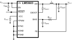
Simplified Schematic

Automotive Power Supply with 5 V, 3 A Output
