SLVSCN6A November 2014 – December 2014 MSP430FR5739-EP
PRODUCTION DATA.
- 1Device Overview
- 2Revision History
- 3Pin Configuration and Functions
-
4Specifications
- 4.1 Absolute Maximum Ratings
- 4.2 Recommended Operating Conditions
- 4.3 Thermal Information
- 4.4 Active Mode Supply Current Into VCC Excluding External Current
- 4.5 Low-Power Mode Supply Currents (Into VCC) Excluding External Current
- 4.6 Schmitt-Trigger Inputs - General Purpose I/O (P1.0 to P1.7, P2.0 to P2.7, P3.0 to P3.7, P4.0 to P4.1, PJ.0 to PJ.5, RST/NMI)
- 4.7 Inputs - Ports P1 and P2 (P1.0 to P1.7, P2.0 to P2.7)
- 4.8 Leakage Current - General Purpose I/O (P1.0 to P1.7, P2.0 to P2.7, P3.0 to P3.7, P4.0 to P4.1, PJ.0 to PJ.5, RST/NMI)
- 4.9 Outputs - General Purpose I/O (P1.0 to P1.7, P2.0 to P2.7, P3.0 to P3.7, P4.0 to P4.1, PJ.0 to PJ.5)
- 4.10 Output Frequency - General Purpose I/O (P1.0 to P1.7, P2.0 to P2.7, P3.0 to P3.7, P4.0 to P4.1, PJ.0 to PJ.5)
- 4.11 Typical Characteristics - Outputs
- 4.12 Crystal Oscillator, XT1, Low-Frequency (LF) Mode
- 4.13 Crystal Oscillator, XT1, High-Frequency (HF) Mode
- 4.14 Internal Very-Low-Power Low-Frequency Oscillator (VLO)
- 4.15 DCO Frequencies
- 4.16 MODOSC
- 4.17 PMM, Core Voltage
- 4.18 PMM, SVS, BOR
- 4.19 Wake-Up from Low Power Modes
- 4.20 Timer_A
- 4.21 Timer_B
- 4.22 eUSCI (UART Mode) Recommended Operating Conditions
- 4.23 eUSCI (UART Mode)
- 4.24 eUSCI (SPI Master Mode) Recommended Operating Conditions
- 4.25 eUSCI (SPI Master Mode)
- 4.26 eUSCI (SPI Slave Mode)
- 4.27 eUSCI (I2C Mode)
- 4.28 10-Bit ADC, Power Supply and Input Range Conditions
- 4.29 10-Bit ADC, Timing Parameters
- 4.30 10-Bit ADC, Linearity Parameters
- 4.31 REF, External Reference
- 4.32 REF, Built-In Reference
- 4.33 REF, Temperature Sensor and Built-In VMID
- 4.34 Comparator_D
- 4.35 FRAM
- 4.36 JTAG and Spy-Bi-Wire Interface
-
5Detailed Description
- 5.1 Functional Block Diagram
- 5.2 CPU
- 5.3 Operating Modes
- 5.4 Interrupt Vector Addresses
- 5.5 Memory Organization
- 5.6 Bootstrap Loader (BSL)
- 5.7 JTAG Operation
- 5.8 FRAM
- 5.9 Memory Protection Unit (MPU)
- 5.10
Peripherals
- 5.10.1 Digital I/O
- 5.10.2 Oscillator and Clock System (CS)
- 5.10.3 Power Management Module (PMM)
- 5.10.4 Hardware Multiplier (MPY)
- 5.10.5 Real-Time Clock (RTC_B)
- 5.10.6 Watchdog Timer (WDT_A)
- 5.10.7 System Module (SYS)
- 5.10.8 DMA Controller
- 5.10.9 Enhanced Universal Serial Communication Interface (eUSCI)
- 5.10.10 TA0, TA1
- 5.10.11 TB0, TB1, TB2
- 5.10.12 ADC10_B
- 5.10.13 Comparator_D
- 5.10.14 CRC16
- 5.10.15 Shared Reference (REF)
- 5.10.16 Embedded Emulation Module (EEM)
- 5.10.17 Peripheral File Map
-
6Input/Output Schematics
- 6.1 Port P1, P1.0 to P1.2, Input/Output With Schmitt Trigger
- 6.2 Port P1, P1.3 to P1.5, Input/Output With Schmitt Trigger
- 6.3 Port P1, P1.6 to P1.7, Input/Output With Schmitt Trigger
- 6.4 Port P2, P2.0 to P2.2, Input/Output With Schmitt Trigger
- 6.5 Port P2, P2.3 to P2.4, Input/Output With Schmitt Trigger
- 6.6 Port P2, P2.5 to P2.6, Input/Output With Schmitt Trigger
- 6.7 Port P2, P2.7, Input/Output With Schmitt Trigger
- 6.8 Port P3, P3.0 to P3.3, Input/Output With Schmitt Trigger
- 6.9 Port P3, P3.4 to P3.6, Input/Output With Schmitt Trigger
- 6.10 Port P3, P3.7, Input/Output With Schmitt Trigger
- 6.11 Port P4, P4.0, Input/Output With Schmitt Trigger
- 6.12 Port P4, P4.1, Input/Output With Schmitt Trigger
- 6.13 Port J, J.0 to J.3 JTAG pins TDO, TMS, TCK, TDI/TCLK, Input/Output With Schmitt Trigger or Output
- 6.14 Port PJ, PJ.4 and PJ.5 Input/Output With Schmitt Trigger
- 7Device Descriptors (TLV)
-
8Device and Documentation Support
- 8.1 Device Support
- 8.2 Documentation Support
- 8.3 Community Resources
- 8.4 Trademarks
- 8.5 Electrostatic Discharge Caution
- 8.6 Glossary
- 9Mechanical Packaging and Orderable Information
パッケージ・オプション
メカニカル・データ(パッケージ|ピン)
- RHA|40
サーマルパッド・メカニカル・データ
- RHA|40
発注情報
8 Device and Documentation Support
8.1 Device Support
8.1.1 Getting Started
TI provides all of the hardware platforms and software components and tooling you need to get started today! Not only that, TI has many complementary components to meet your needs. For an overview of the MSP430™ MCU product line, the available development tools and evaluation kits, and advanced development resources, visit the MSP430 Getting Started page.
8.1.2 Development Tools Support
All MSP430™ microcontrollers are supported by a wide variety of software and hardware development tools. Tools are available from TI and various third parties. See them all at www.ti.com/msp430tools.
8.1.2.1 Hardware Features
See the Code Composer Studio for MSP430 User's Guide (SLAU157) for details on the available features.
| MSP430 Architecture | 4-Wire JTAG | 2-Wire JTAG | Break- points (N) |
Range Break- points | Clock Control | State Sequencer | Trace Buffer | LPMx.5 Debugging Support |
|---|---|---|---|---|---|---|---|---|
| MSP430Xv2 | Yes | Yes | 3 | Yes | Yes | No | No | Yes |
8.1.2.2 Recommended Hardware Options
8.1.2.2.1 Target Socket Boards
The target socket boards allow easy programming and debugging of the device using JTAG. They also feature header pin outs for prototyping. Target socket boards are orderable individually or as a kit with the JTAG programmer and debugger included. The following table shows the compatible target boards and the supported packages.
| Package | Target Board and Programmer Bundle | Target Board Only |
|---|---|---|
| 40-pin VQFN (RHA) | MSP-FET430U40A | MSP-TS430RHA40A |
8.1.2.2.2 Experimenter Boards
Experimenter Boards and Evaluation kits are available for some MSP430 devices. These kits feature additional hardware components and connectivity for full system evaluation and prototyping. See www.ti.com/msp430tools for details.
8.1.2.2.3 Debugging and Programming Tools
Hardware programming and debugging tools are available from TI and from its third party suppliers. See the full list of available tools at www.ti.com/msp430tools.
8.1.2.2.4 Production Programmers
The production programmers expedite loading firmware to devices by programming several devices simultaneously.
| Part Number | PC Port | Features | Provider |
|---|---|---|---|
| MSP-GANG | Serial and USB | Program up to eight devices at a time. Works with PC or standalone. | Texas Instruments |
8.1.2.3 Recommended Software Options
8.1.2.3.1 Integrated Development Environments
Software development tools are available from TI or from third parties. Open source solutions are also available.
This device is supported by Code Composer Studio™ IDE (CCS).
8.1.2.3.2 MSP430Ware
MSP430Ware is a collection of code examples, data sheets, and other design resources for all MSP430 devices delivered in a convenient package. In addition to providing a complete collection of existing MSP430 design resources, MSP430Ware also includes a high-level API called MSP430 Driver Library. This library makes it easy to program MSP430 hardware. MSP430Ware is available as a component of CCS or as a standalone package.
8.1.2.3.3 Command-Line Programmer
MSP430 Flasher is an open-source, shell-based interface for programming MSP430 microcontrollers through a FET programmer or eZ430 using JTAG or Spy-Bi-Wire (SBW) communication. MSP430 Flasher can be used to download binary files (.txt or .hex) files directly to the MSP430 microcontroller without the need for an IDE.
8.1.3 Device and Development Tool Nomenclature
To designate the stages in the product development cycle, TI assigns prefixes to the part numbers of all MSP430 MCU devices and support tools. Each MSP430 MCU commercial family member has one of three prefixes: MSP, PMS, or XMS (for example, MSP430F5259). Texas Instruments recommends two of three possible prefix designators for its support tools: MSP and MSPX. These prefixes represent evolutionary stages of product development from engineering prototypes (with XMS for devices and MSPX for tools) through fully qualified production devices and tools (with MSP for devices and MSP for tools).
Device development evolutionary flow:
XMS – Experimental device that is not necessarily representative of the final device's electrical specifications
PMS – Final silicon die that conforms to the device's electrical specifications but has not completed quality and reliability verification
MSP – Fully qualified production device
Support tool development evolutionary flow:
MSPX – Development-support product that has not yet completed Texas Instruments internal qualification testing.
MSP – Fully-qualified development-support product
XMS and PMS devices and MSPX development-support tools are shipped against the following disclaimer:
"Developmental product is intended for internal evaluation purposes."
MSP devices and MSP development-support tools have been characterized fully, and the quality and reliability of the device have been demonstrated fully. TI's standard warranty applies.
Predictions show that prototype devices (XMS and PMS) have a greater failure rate than the standard production devices. Texas Instruments recommends that these devices not be used in any production system because their expected end-use failure rate still is undefined. Only qualified production devices are to be used.
TI device nomenclature also includes a suffix with the device family name. This suffix indicates the package type (for example, PZP) and temperature range (for example, T). Figure 8-1 provides a legend for reading the complete device name for any family member.
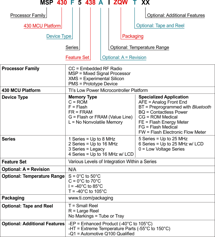 Figure 8-1 Device Nomenclature
8.2 Documentation Support
The following documents describe the MSP430FR5739-EP MCU. Copies of these documents are available on www.ti.com.
-
SLAU272MSP430FR57xx Family User's Guide. Detailed description of all modules and peripherals available in this device family.
-
SLAZ392MSP430FR5739 Device Erratasheet. Describes the known exceptions to the functional specifications for each silicon revision of this device.
-
SLAZ391MSP430FR5738 Device Erratasheet. Describes the known exceptions to the functional specifications for each silicon revision of this device.
-
SLAZ390MSP430FR5737 Device Erratasheet. Describes the known exceptions to the functional specifications for each silicon revision of this device.
-
SLAZ389MSP430FR5736 Device Erratasheet. Describes the known exceptions to the functional specifications for each silicon revision of this device.
-
SLAZ388MSP430FR5735 Device Erratasheet. Describes the known exceptions to the functional specifications for each silicon revision of this device.
-
SLAZ387MSP430FR5734 Device Erratasheet. Describes the known exceptions to the functional specifications for each silicon revision of this device.
-
SLAZ386MSP430FR5733 Device Erratasheet. Describes the known exceptions to the functional specifications for each silicon revision of this device.
-
SLAZ385MSP430FR5732 Device Erratasheet. Describes the known exceptions to the functional specifications for each silicon revision of this device.
-
SLAZ384MSP430FR5731 Device Erratasheet. Describes the known exceptions to the functional specifications for each silicon revision of this device.
-
SLAZ383MSP430FR5730 Device Erratasheet. Describes the known exceptions to the functional specifications for each silicon revision of this device.
8.3 Community Resources
The following links connect to TI community resources. Linked contents are provided "AS IS" by the respective contributors. They do not constitute TI specifications and do not necessarily reflect TI's views; see TI's Terms of Use.
TI E2E™ Community
TI's Engineer-to-Engineer (E2E) Community. Created to foster collaboration among engineers. At e2e.ti.com, you can ask questions, share knowledge, explore ideas, and help solve problems with fellow engineers.
TI Embedded Processors Wiki
Texas Instruments Embedded Processors Wiki. Established to help developers get started with embedded processors from Texas Instruments and to foster innovation and growth of general knowledge about the hardware and software surrounding these devices.
8.4 Trademarks
Code Composer Studio, MSP430, E2E are trademarks of Texas Instruments.
All other trademarks are the property of their respective owners.
8.5 Electrostatic Discharge Caution

This integrated circuit can be damaged by ESD. Texas Instruments recommends that all integrated circuits be handled with appropriate precautions. Failure to observe proper handling and installation procedures can cause damage.
ESD damage can range from subtle performance degradation to complete device failure. Precision integrated circuits may be more susceptible to damage because very small parametric changes could cause the device not to meet its published specifications.
8.6 Glossary
SLYZ022 — TI Glossary.
This glossary lists and explains terms, acronyms, and definitions.