JAJS198L October 2006 – January 2020 OPA211
PRODUCTION DATA.
- 1 特長
- 2 アプリケーション
- 3 概要
- 4 改訂履歴
- 5 概要(続き)
- 6 Pin Configuration and Functions
-
7 Specifications
- 7.1 Absolute Maximum Ratings
- 7.2 ESD Ratings
- 7.3 Recommended Operating Conditions
- 7.4 Thermal Information: OPA211 and OPA211A
- 7.5 Thermal Information: OPA2211 and OPA2211A
- 7.6 Electrical Characteristics: Standard Grade OPAx211A
- 7.7 Electrical Characteristics: High-Grade OPAx211
- 7.8 Typical Characteristics
- 8 Detailed Description
- 9 Application and Implementation
- 10Power Supply Recommendations
- 11Layout
- 12デバイスおよびドキュメントのサポート
- 13メカニカル、パッケージ、および注文情報
パッケージ・オプション
メカニカル・データ(パッケージ|ピン)
サーマルパッド・メカニカル・データ
発注情報
8.3.1 Total Harmonic Distortion Measurements
OPA211 series operational amplifiers have excellent distortion characteristics. THD + noise is below 0.0001% (G = 1, VO = 3 VRMS) throughout the audio frequency range, 20 Hz to 20 kHz, with a 600-Ω load.
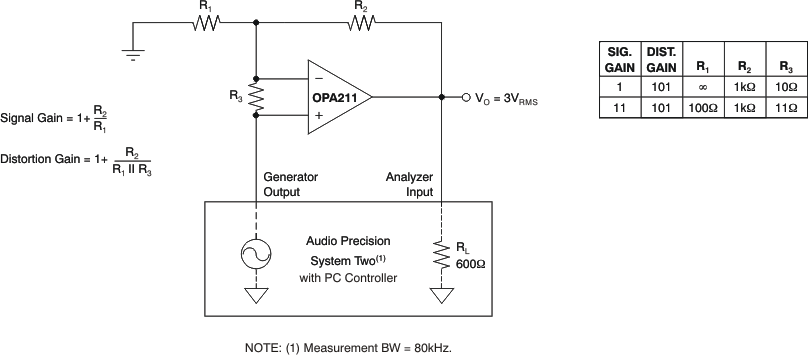
The distortion produced by OPAx211 series operational amplifiers is below the measurement limit of many commercially available distortion analyzers. However, a special test circuit shown in Figure 43 can extend the measurement capabilities.
Operational amplifier distortion can be considered an internal error source that can be referred to the input. Figure 43 shows a circuit that causes the operational amplifier distortion to be 101 times greater than that normally produced by the operational amplifier. The addition of R3 to the otherwise standard noninverting amplifier configuration alters the feedback factor or noise gain of the circuit. The closed-loop gain is unchanged, but the feedback available for error correction is reduced by a factor of 101, thus extending the resolution by 101.
NOTE
The input signal and load applied to the operational amplifier are the same as with conventional feedback without R3. The value of R3 should be kept small to minimize its effect on the distortion measurements.
Validity of this technique can be verified by duplicating measurements at high gain and/or high frequency where the distortion is within the measurement capability of the test equipment. Measurements for this data sheet were made with an Audio Precision System Two distortion/noise analyzer, which greatly simplifies such repetitive measurements. The measurement technique can, however, be performed with manual distortion measurement instruments.
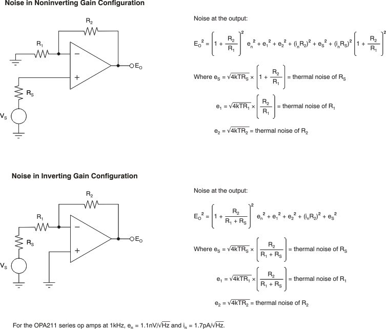
 Figure 42. Noise Calculation in Gain Configurations
  Figure 43. Distortion Test Circuit