JAJSFZ4E March 2009 – August 2018 TMS320C28341 , TMS320C28342 , TMS320C28343 , TMS320C28344 , TMS320C28345 , TMS320C28346
PRODUCTION DATA.
- 1デバイスの概要
- 2改訂履歴
- 3Device Comparison
- 4Terminal Configuration and Functions
-
5Specifications
- 5.1 Absolute Maximum Ratings
- 5.2 ESD Ratings – Automotive
- 5.3 ESD Ratings – Commercial
- 5.4 Recommended Operating Conditions
- 5.5 Power Consumption Summary
- 5.6 Electrical Characteristics
- 5.7 Thermal Resistance Characteristics
- 5.8 Thermal Design Considerations
- 5.9
Timing and Switching Characteristics
- 5.9.1 Timing Parameter Symbology
- 5.9.2 Power Sequencing
- 5.9.3 Clock Requirements and Characteristics
- 5.9.4
Peripherals
- 5.9.4.1 General-Purpose Input/Output (GPIO)
- 5.9.4.2 Enhanced Control Peripherals
- 5.9.4.3 External Interrupt Timing
- 5.9.4.4 I2C Electrical Specification and Timing
- 5.9.4.5 Serial Peripheral Interface (SPI) Timing
- 5.9.4.6
Multichannel Buffered Serial Port (McBSP) Timing
- 5.9.4.6.1 McBSP Transmit and Receive Timing
- 5.9.4.6.2
McBSP as SPI Master or Slave Timing
- Table 5-36 McBSP as SPI Master or Slave Timing Requirements (CLKSTP = 10b, CLKXP = 0)
- Table 5-37 McBSP as SPI Master or Slave Switching Characteristics (CLKSTP = 10b, CLKXP = 0)
- Table 5-38 McBSP as SPI Master or Slave Timing Requirements (CLKSTP = 11b, CLKXP = 0)
- Table 5-39 McBSP as SPI Master or Slave Switching Characteristics (CLKSTP = 11b, CLKXP = 0)
- Table 5-40 McBSP as SPI Master or Slave Timing Requirements (CLKSTP = 10b, CLKXP = 1)
- Table 5-41 McBSP as SPI Master or Slave Switching Characteristics (CLKSTP = 10b, CLKXP = 1)
- Table 5-42 McBSP as SPI Master or Slave Timing Requirements (CLKSTP = 11b, CLKXP = 1)
- Table 5-43 McBSP as SPI Master or Slave Switching Characteristics (CLKSTP = 11b, CLKXP = 1)
- 5.9.5 Emulator Connection Without Signal Buffering for the MCU
- 5.9.6
External Interface (XINTF) Timing
- 5.9.6.1 USEREADY = 0
- 5.9.6.2 Synchronous Mode (USEREADY = 1, READYMODE = 0)
- 5.9.6.3 Asynchronous Mode (USEREADY = 1, READYMODE = 1)
- 5.9.6.4 XINTF Signal Alignment to XCLKOUT
- 5.9.6.5 External Interface Read Timing
- 5.9.6.6 External Interface Write Timing
- 5.9.6.7
External Interface Ready-on-Read Timing With One External Wait State
- Table 5-49 External Interface Read Switching Characteristics (Ready-on-Read, One Wait State)
- Table 5-50 External Interface Read Timing Requirements (Ready-on-Read, One Wait State)
- Table 5-51 Synchronous XREADY Timing Requirements (Ready-on-Read, One Wait State)
- Table 5-52 Asynchronous XREADY Timing Requirements (Ready-on-Read, One Wait State)
- 5.9.6.8 External Interface Ready-on-Write Timing With One External Wait State
- 5.9.6.9 XHOLD and XHOLDA Timing
-
6Detailed Description
- 6.1
Brief Descriptions
- 6.1.1 C28x CPU
- 6.1.2 Memory Bus (Harvard Bus Architecture)
- 6.1.3 Peripheral Bus
- 6.1.4 Real-Time JTAG and Analysis
- 6.1.5 External Interface (XINTF)
- 6.1.6 M0, M1 SARAMs
- 6.1.7 L0, L1, L2, L3, L4, L5, L6, L7, H0, H1, H2, H3, H4, H5 SARAMs
- 6.1.8 Boot ROM
- 6.1.9 Security
- 6.1.10 Peripheral Interrupt Expansion (PIE) Block
- 6.1.11 External Interrupts (XINT1–XINT7, XNMI)
- 6.1.12 Oscillator and PLL
- 6.1.13 Watchdog
- 6.1.14 Peripheral Clocking
- 6.1.15 Low-Power Modes
- 6.1.16 Peripheral Frames 0, 1, 2, 3 (PFn)
- 6.1.17 General-Purpose Input/Output (GPIO) Multiplexer
- 6.1.18 32-Bit CPU-Timers (0, 1, 2)
- 6.1.19 Control Peripherals
- 6.1.20 Serial Port Peripherals
- 6.2
Peripherals
- 6.2.1 DMA Overview
- 6.2.2 32-Bit CPU-Timer 0, CPU-Timer 1, CPU-Timer 2
- 6.2.3 Enhanced PWM Modules
- 6.2.4 High-Resolution PWM (HRPWM)
- 6.2.5 Enhanced CAP Modules
- 6.2.6 Enhanced QEP Modules
- 6.2.7 External ADC Interface
- 6.2.8 Multichannel Buffered Serial Port (McBSP) Module
- 6.2.9 Enhanced Controller Area Network (eCAN) Modules (eCAN-A and eCAN-B)
- 6.2.10 Serial Communications Interface (SCI) Modules (SCI-A, SCI-B, SCI-C)
- 6.2.11 Serial Peripheral Interface (SPI) Module (SPI-A, SPI-D)
- 6.2.12 Inter-Integrated Circuit (I2C)
- 6.2.13 GPIO MUX
- 6.2.14 External Interface (XINTF)
- 6.3 Memory Maps
- 6.4 Register Map
- 6.5 Interrupts
- 6.6 System Control
- 6.7 Low-Power Modes Block
- 6.1
Brief Descriptions
- 7Applications, Implementation, and Layout
- 8デバイスおよびドキュメントのサポート
- 9メカニカル、パッケージ、および注文情報
パッケージ・オプション
デバイスごとのパッケージ図は、PDF版データシートをご参照ください。
メカニカル・データ(パッケージ|ピン)
- ZFE|256
サーマルパッド・メカニカル・データ
発注情報
8.2 デバイスおよび開発ツールの項目表記
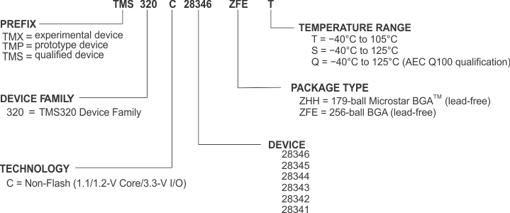
製品開発サイクルの段階を示すために、TIではTMS320™ MCUデバイスおよびサポート・ツールのすべての型番に接頭辞を割り当てています。それぞれのTMS320™ の商用ファミリ・メンバには、TMX、TMP、TMSのいずれかの接頭辞があります(たとえば、TMS320C28345)。テキサス・インスツルメンツは、サポート・ツールに使用可能な3つの接頭辞のうち、TMDXおよびTMDSの2つを推奨しています。これらの接頭辞は、製品開発の進展段階を表します。段階には、エンジニアリング・プロトタイプ(TMX/TMDX)から、認定済み製品デバイス/ツール(TMS/TMDS)があります。
デバイス開発の段階は次のとおりです。
| TMX | 実験的デバイスで、最終デバイスの電気的特性を必ずしも表しません。 | |
| TMP | 最終的なシリコン・ダイで、デバイスの電気的特性に適合しますが、品質および信頼性の検証は完了していません。 | |
| TMS | 完全に認定済みの量産版デバイスです。 |
サポート・ツール開発の段階は次のとおりです。
| TMDX | 開発サポート製品で、テキサス・インスツルメンツの社内認定試験はまだ完了していません。 | |
| TMDS | 完全に認定済みの開発サポート製品です。 |
TMXおよびTMPデバイスと、TMDX開発サポート・ツールは、以下の免責事項の下で出荷されます。
「開発段階の製品は、社内での評価を目的としたものです」
TMSデバイスとTMDS開発サポート・ツールの特性は完全に明確化されており、デバイスの品質と信頼性が十分に示されてきました。TIの標準保証が適用されます。
プロトタイプ・デバイス(TMXまたはTMP)の方が標準的な製品版デバイスに比べて故障率が大きいと予測されます。これらのデバイスは予測される最終使用時の故障率が未定義であるため、テキサス・インスツルメンツではそれらのデバイスを量産システムで使用しないよう推奨しています。認定された量産デバイスのみを使用する必要があります。
TIデバイスの項目表記には、デバイス・ファミリ名の接尾辞も含まれます。この接尾辞は、パッケージ・タイプ(たとえば、ZFE)および温度範囲(たとえば、T)を示しています。Figure 8-1に、任意のファミリ・メンバについて、完全なデバイス名を読み取るための凡例を示します。
デバイスの型番、および注文情報の詳細については、このデータシートにあるパッケージ・オプションについての付録や、TI Webサイト(www.ti.com)を参照するか、またはお近くのTI販売代理店にお問い合わせください。
ダイに記されているデバイス項目表記マーキングの詳細説明については、『TMS320C2834x Delfino™ MCUシリコン正誤表』SPRZ267を参照してください。
