JAJSL03C January   2021  – December 2021 TPS61094

PRODUCTION DATA  

  1. 特長
  2. アプリケーション
  3. 概要
  4. Revision History
  5. Pin Configuration and Functions
  6. Specifications
    1. 6.1 Absolute Maximum Ratings
    2. 6.2 ESD Ratings
    3. 6.3 Recommended Operating Conditions
    4. 6.4 Thermal Information
    5. 6.5 Electrical Characteristics
    6. 6.6 Typical Characteristics
  7. Detailed Description
    1. 7.1 Overview
      1. 7.1.1 The Configuration of VCHG Pin, ICHG Pin, and OSEL Pin
        1. 7.1.1.1 OSEL: Output Voltage Selection
        2. 7.1.1.2 VCHG: Charging Termination Voltage Selection
        3. 7.1.1.3 ICHG: Charging Output Current Selection
    2. 7.2 Functional Block Diagram
    3. 7.3 Feature Description
      1. 7.3.1 Undervoltage Lockout
      2. 7.3.2 Enable and Soft Start
      3. 7.3.3 Active Pulldown for the EN and MODE Pins
      4. 7.3.4 Current Limit Operation
      5. 7.3.5 Output Short-to-Ground Protection
      6. 7.3.6 Thermal Shutdown
    4. 7.4 Device Functional Modes
      1. 7.4.1 Operation Mode Setting
      2. 7.4.2 Forced Bypass Mode Operation
      3. 7.4.3 True Shutdown Mode Operation
      4. 7.4.4 Forced Buck Mode Operation
      5. 7.4.5 Auto Buck or Boost Mode Operation
        1. 7.4.5.1 Three States (Boost_on, Buck_on, and Supplement) Transition
        2. 7.4.5.2 Boost, Bypass, and Pass-Through
        3. 7.4.5.3 PWM, PFM, and Snooze Modes in Boost Operation
          1. 7.4.5.3.1 PWM Mode
          2. 7.4.5.3.2 PFM Mode
          3. 7.4.5.3.3 Snooze Mode
  8. Application and Implementation
    1. 8.1 Application Information
    2. 8.2 Typical Application – 3.6-V Output Boost Converter with Bypass
      1. 8.2.1 Design Requirements
      2. 8.2.2 Detailed Design Procedure
        1. 8.2.2.1 Programming the Output Voltage
        2. 8.2.2.2 Maximum Output Current
        3. 8.2.2.3 Inductor Selection
        4. 8.2.2.4 Output Capacitor Selection
        5. 8.2.2.5 Input Capacitor Selection
      3. 8.2.3 Application Curves
      4. 8.2.4 Typical Application – 3.3-V Output Boost Converter with Automatic Buck or Boost Function
        1. 8.2.4.1 Design Requirements
        2. 8.2.4.2 Detailed Design Procedure
          1. 8.2.4.2.1 Programming the Voltage and Current
        3. 8.2.4.3 Application Curves
  9. Power Supply Recommendations
  10. 10Layout
    1. 10.1 Layout Guidelines
    2. 10.2 Layout Example
  11. 11Device and Documentation Support
    1. 11.1 Device Support
      1. 11.1.1 Third-Party Products Disclaimer
    2. 11.2 Documentation Support
      1. 11.2.1 Related Documentation
    3. 11.3 Receiving Notification of Documentation Updates
    4. 11.4 サポート・リソース
    5. 11.5 Trademarks
    6. 11.6 Electrostatic Discharge Caution
    7. 11.7 Glossary
  12. 12Mechanical, Packaging, and Orderable Information

パッケージ・オプション

メカニカル・データ(パッケージ|ピン)
サーマルパッド・メカニカル・データ
発注情報

概要

TPS61094 は、60nA の IQで、スーパーキャパシタ管理機能を搭載した昇圧コンバータです。このデバイスは、スマート・メーター・アプリケーションやスーパーキャパシタ・バックアップ電源アプリケーション向けの電源ソリューションを実現します。

TPS61094 は入力電圧範囲が広く、最大 5.5V の出力電圧を供給できます。TPS61094 を降圧モードで使用してスーパーキャパシタを充電する場合、2 個の外付け抵抗によって充電電流と充電終了電圧をプログラムできます。TPS61094 を昇圧モードで動作させる場合、1 個の外付け抵抗を使って出力電圧をプログラムできます。

自動昇降圧モード (EN = 1、MODE = 1) 中に入力電源が印加されると、本デバイスは入力電圧を出力にバイパスし、同時にバックアップ・スーパーキャパシタを充電できます。入力電源が切り離された場合、または出力目標電圧を下回った場合、TPS61094 は昇圧モードに遷移し、バックアップ・スーパーキャパシタから出力電圧をレギュレートします。このモードでは、TPS61094 は 60nA の静止電流を消費します。

TPS61094 は真のシャットダウン・モード (EN = 0、MODE = 1) と強制バイパス・モード (EN = 0、MODE = 0) をサポートしています。真のシャットダウン・モードでは、TPS61094 は負荷を入力電源から完全に切り離します。強制バイパス・モードでは、TPS61094 はバイパス・スイッチ経由で負荷を入力電圧に直接接続することで消費電流を 4nA に低減し、バッテリ寿命を延長します。

製品情報
部品番号 パッケージ(1) 本体サイズ (公称)
TPS61094 WSON (12) 2.0mm × 3.0mm
利用可能なすべてのパッケージについては、このデータシートの末尾にある注文情報を参照してください。
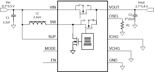
代表的なアプリケーション回路 1
GUID-20200831-CA0I-V9L5-NGLG-JSSD3RN4H494-low.gif代表的なアプリケーション回路 2